Educational Material
1.3 MEMS Operation
Up until the emergence of microelectromechanical systems (MEMS) technology, inertial sensors were high-cost, precision instruments, typically reserved for high-end applications. As MEMS technology has matured, low-cost solid-state chip level inertial sensors have become available as alternatives to the larger high-end inertial sensors. This addition of MEMS to the inertial sensing market has provided a wide variety of performance capabilities and allowed inertial sensing technology to be used in more applications than ever before.
MEMS Accelerometers
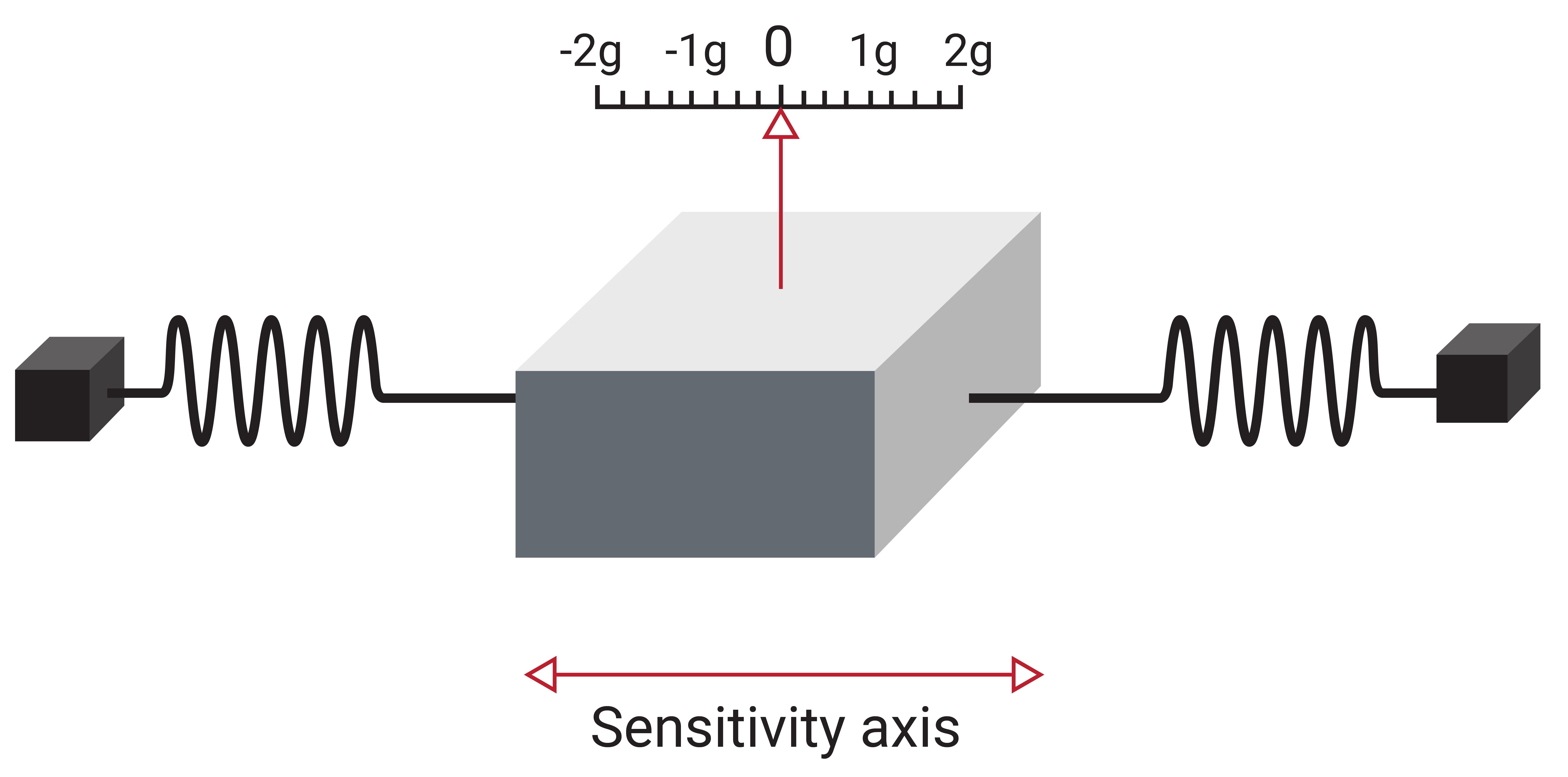
An accelerometer is the primary sensor responsible for measuring inertial acceleration, or the change in velocity over time, and can be found in a variety of different types, including mechanical accelerometers, quartz accelerometers, and MEMS accelerometers. A MEMS accelerometer is essentially a mass suspended by a spring, as illustrated in Figure 1.6a. The mass is known as the proof mass and the direction that the mass is allowed to move is known as the sensitivity axis.
When an accelerometer is subjected to a linear acceleration along the sensitivity axis, the acceleration causes the proof mass to shift to one side, with the amount of deflection proportional to the acceleration.
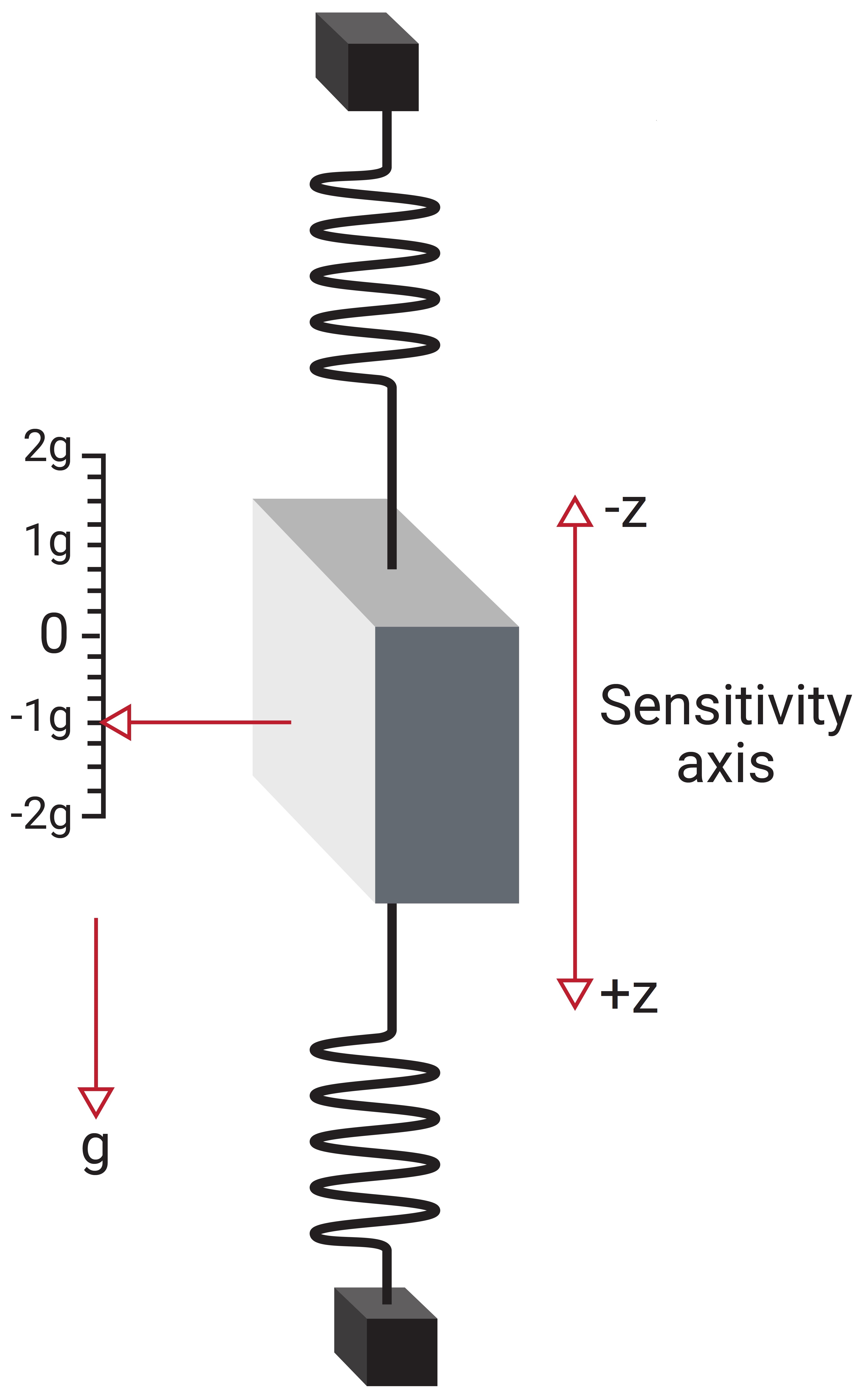
Now consider that the accelerometer is rotated such that the sensitivity axis is aligned with the gravity vector, as shown in Figure 1.6b. In this case, gravity acts on the proof mass causing it to deflect downward. Due to this, the accelerometer measures both the linear acceleration due to motion as well as the pseudo-acceleration caused by gravity. The acceleration caused by gravity is referred to as a pseudo-acceleration as it does not actually result in a change in velocity or position.
In the coordinate frame shown in Figure 1.6b, the pseudo-acceleration caused by gravity is measured as a -1 g, as gravity has the same effect on the accelerometer as an acceleration due to motion in the negative z-axis. It is also important to note that during free fall, the springs in the accelerometer do not deflect, and consequently the sensor reports an acceleration of zero, though the actual acceleration is non-zero.
MEMS Gyroscopes
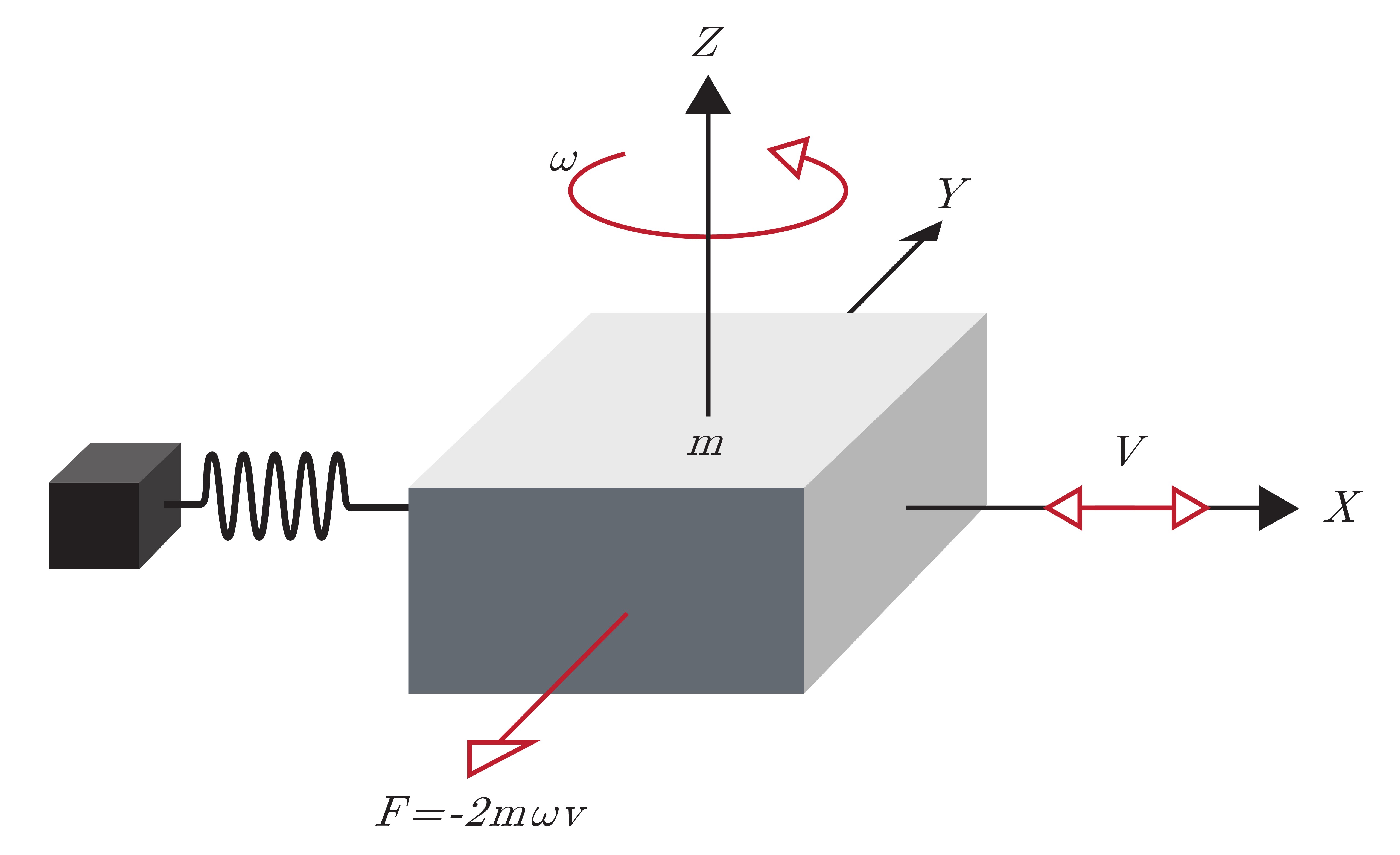
A gyroscope is an inertial sensor that measure an object's angular rate with respect to an inertial reference frame. MEMS gyroscopes measures the angular rate by applying the theory of the Coriolis effect, which refers to the force of inertia that acts on objects in motion in relation to a rotating frame. To better understand, consider a mass suspended on springs, as illustrated in Figure 1.7a. This mass has a driving force on the x-axis causing it to oscillate rapidly in the x-axis. While in motion an angular velocity, $\omega$, is applied about the z-axis. This results in the mass experiencing a force in the y-axis as a result of the Coriolis force, and the resultant displacement is measured by a capacitive-sensing structure.
A quick derivation of this Coriolis force may provide further clarity. The position of the mass, $m$, in the body frame is given by Equation \ref{eq:gypos}:
\begin{equation} \label{eq:gypos} ^B\boldsymbol{r} = \left[\begin{matrix} x\\ y \end{matrix}\right]\end{equation}
The inertial velocity of the mass in the body frame is then defined as the derivative of the position plus the tangential velocity due to rotation.
\begin{equation} ^B\boldsymbol{\dot{r}} = \left[\begin{matrix} \dot{x}\\ \dot{y} \end{matrix}\right] +{}^B\boldsymbol{\omega} \times{}^B\boldsymbol{r} = \left[\begin{matrix} \dot{x} - \omega y\\ \dot{y} + \omega x \end{matrix}\right]\end{equation}
The inertial acceleration of the mass in the body frame can be described as the derivative of the velocity plus the tangential acceleration due to rotation.
\begin{equation} \label{eq:gyac} ^B\boldsymbol{\ddot{r}} = \begin{bmatrix} \ddot{x} - \omega\dot{y}\\ \ddot{y} + \omega\dot{x} \end{bmatrix} +{}^B\boldsymbol{\omega} \times{}^B\dot{\boldsymbol{r}} = \begin{bmatrix} \ddot{x} - 2\omega\dot{y} - \omega^2x\\ \ddot{y} + 2\omega\dot{x} - \omega^2y \end{bmatrix}\end{equation}
The first element in Equation \ref{eq:gyac} represents the acceleration experienced by the driven axis, which is actively controlled by the gyroscope's electronics. The second element in Equation \ref{eq:gyac} represents the acceleration from the sensing axis of the gyroscope. From Newton's Second Law of Motion, the sum of the forces in the sensing direction is equal to the product of the mass of the block, $m$, and the acceleration in the sensing direction, $\ddot{r}_y$:
\begin{equation} F_y = m{}^B\ddot{r}_y = m(\ddot{y} + 2\omega\dot{x} - \omega^2y) \end{equation}
For illustrative purposes, if the mass starts from rest in the y-axis ($y = \dot{y} = \ddot{y} = 0$), the sum of the forces in the y-axis reduces down to only the Coriolis term, $F_y=2m\omega\dot{x}$. Since the mass is driven in the x-axis at high frequency (10s of kHz), the value of $\dot{x}$ is significant and the Coriolis effect causes significant, oscillatory displacement in the y-axis proportional to the angular rate.
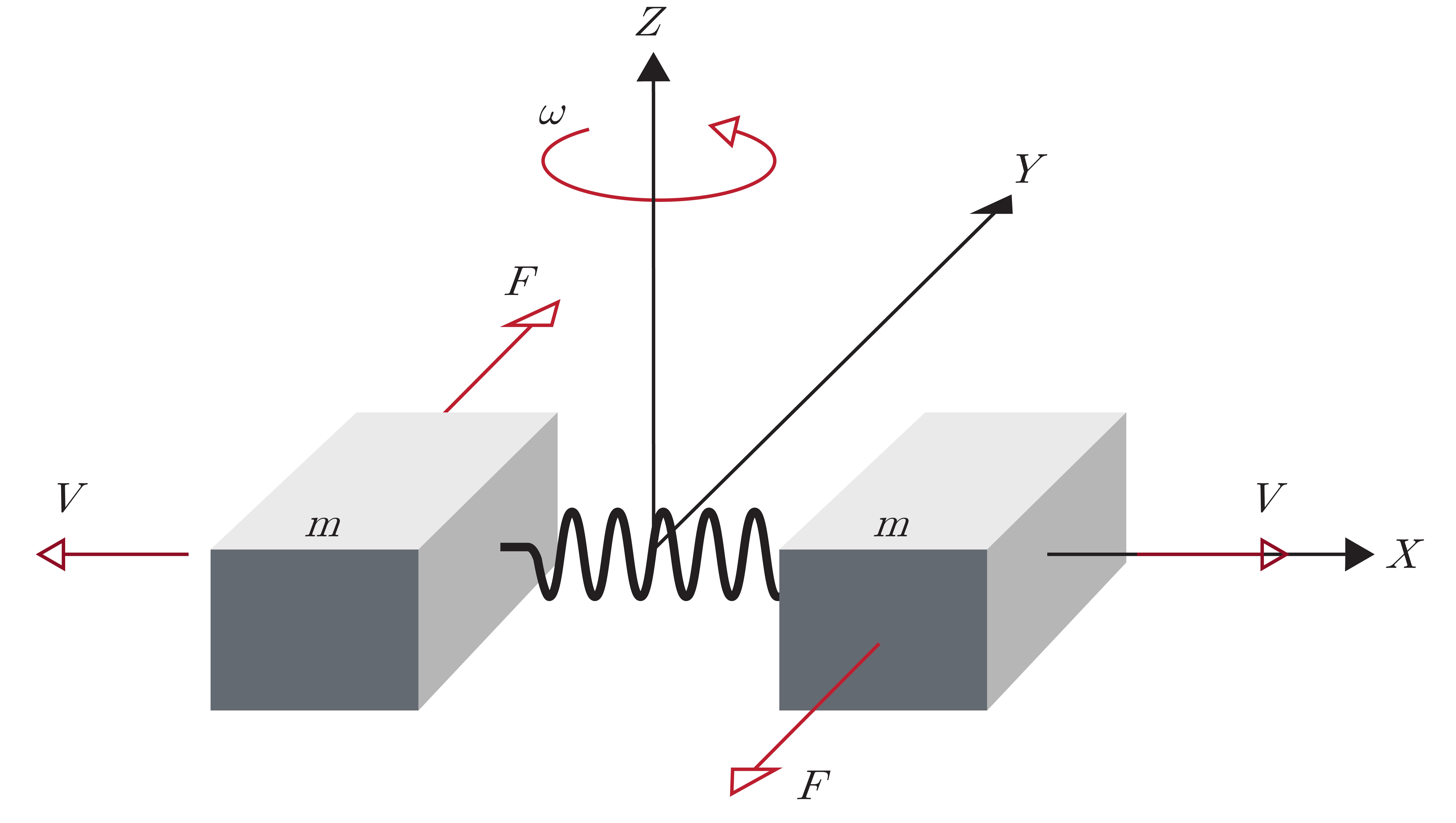
Typically, MEMS gyroscopes use a tuning fork configuration in which two masses are connected by a spring, as shown in Figure 1.7b. When an angular rate is applied, the Coriolis force on each mass acts in the opposite direction and the resulting change in capacitance is directly proportional to the angular velocity. However, when a linear acceleration is applied, the two masses moves in the same direction, resulting in no change in capacitance and a measured angular rate of zero. This configuration minimizes a gyroscope's sensitivity to linear acceleration from instances of shock, vibration, and tilt.
MEMS Magnetometers
A magnetometer is a type of sensor that measures the strength and direction of a magnetic field. While there are many different types of magnetometers, most MEMS magnetometers rely on magnetoresistance to measure the surrounding magnetic field. Magnetoresistive magnetometers are made up of permalloys that change resistance due to changes in magnetic fields. Typically, MEMS magnetometers are used to measure a local magnetic field which consists of a combination of Earth's magnetic field as well as any magnetic fields created by nearby objects.
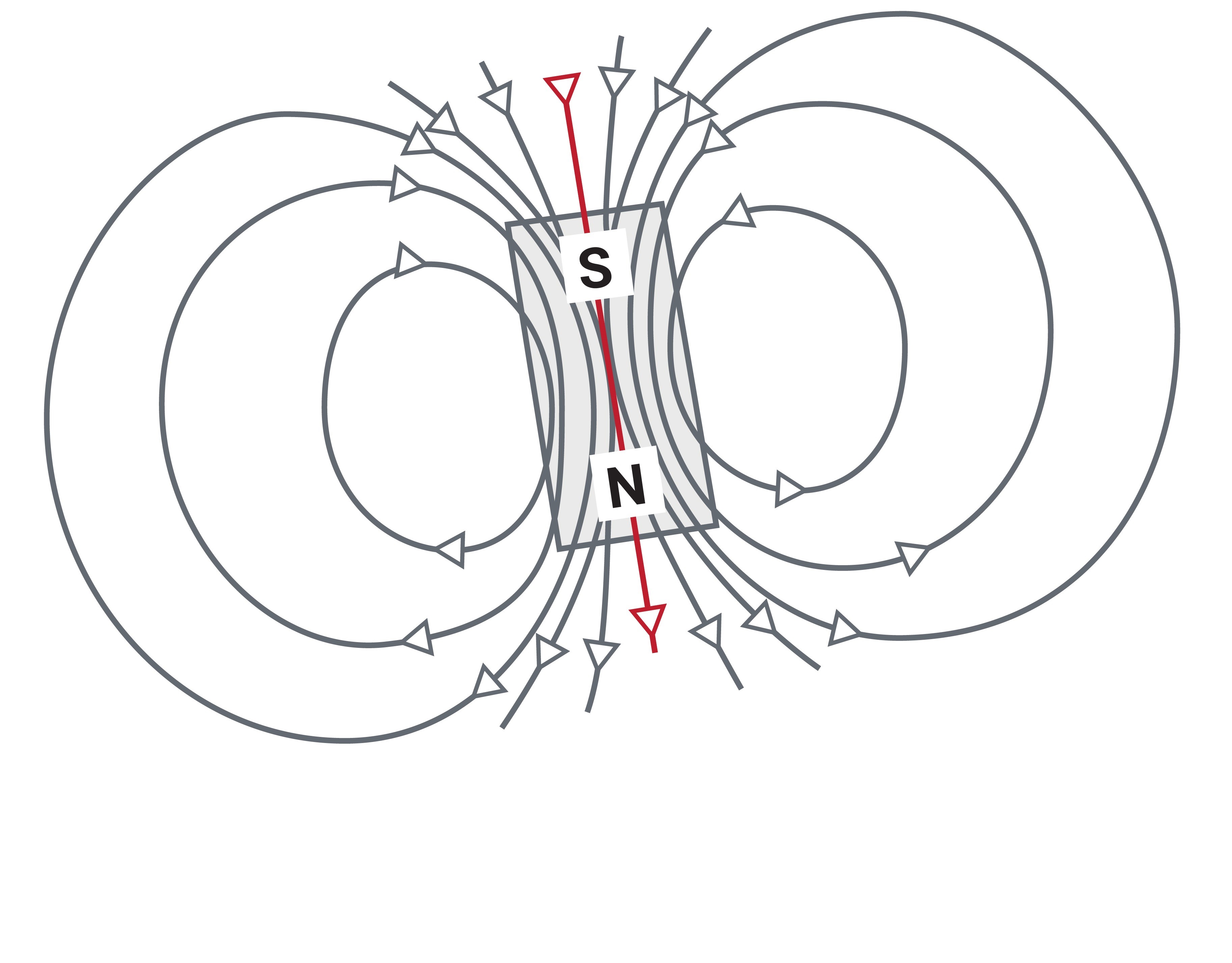
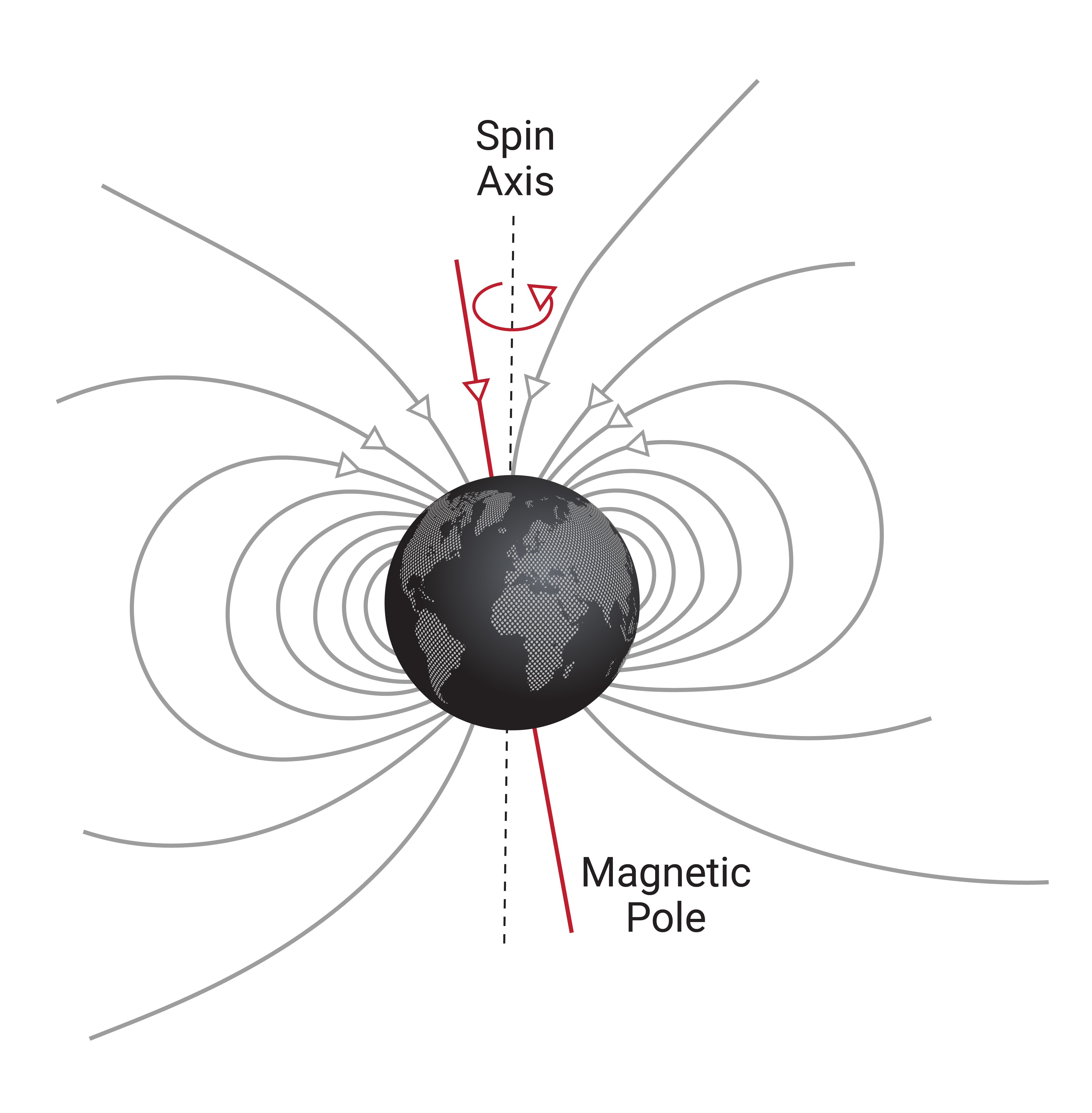
As illustrated in Figure 1.8, Earth's magnetic field is a self-sustaining magnetic field that resembles a magnetic dipole with the geomagnetic poles slightly offset from the geographic North and South poles. This magnetic field is characterized by a strength and direction, which varies across the earth and can shift over time.
The direction of Earth's magnetic field contains a horizontal component as well as a vertical component and is often described using the magnetic inclination and declination angles. Magnetic inclination describes the angle between Earth's magnetic field lines and a horizontal plane. At Earth's magnetic poles the magnetic field is vertical and has an inclination angle of 90°, whereas Earth's magnetic field is horizontal at the equator and has an inclination angle of 0°. The magnetic declination is used to account for the fact that the magnetic North Pole of the earth is not in the same location as True North or the geographic North Pole of the earth and is characterized as the angle between these two locations, relative to the point of measurement.
