Educational Material
1.1 Inertial Sensors
Inertial sensors have been used for over a century to measure the motion of an object with respect to an inertial reference frame. When first created, inertial sensors consisted of large mechanical gyroscopes and accelerometers. However, since the early 1930s, numerous scientists, engineers, and institutions have been perfecting this technology, creating a wide variety of inertial sensors with various performance capabilities which has allowed them to be used today in more applications than ever before.
Grades of Inertial Sensors
The inertial sensor market spans an enormous range in terms of product price and performance between the highest-end inertial systems and the lowest. This wide variety can lead to great confusion for many customers when determining component selection and pricing. In addition, there are no agreed-upon definitions or standards of high-, medium-, and low-grade performance when it comes to inertial sensors, so what one expert considers high-end may be the low-end to another. However, in general, inertial sensors can be grouped into one of the following four performance categories:
- Navigation Grade
- Tactical Grade
- Industrial Grade
- Automotive/Consumer Grade
These performance categories are typically defined based on the in-run bias stability of the sensor, as the in-run bias stability plays such a large role in determining inertial navigation performance.
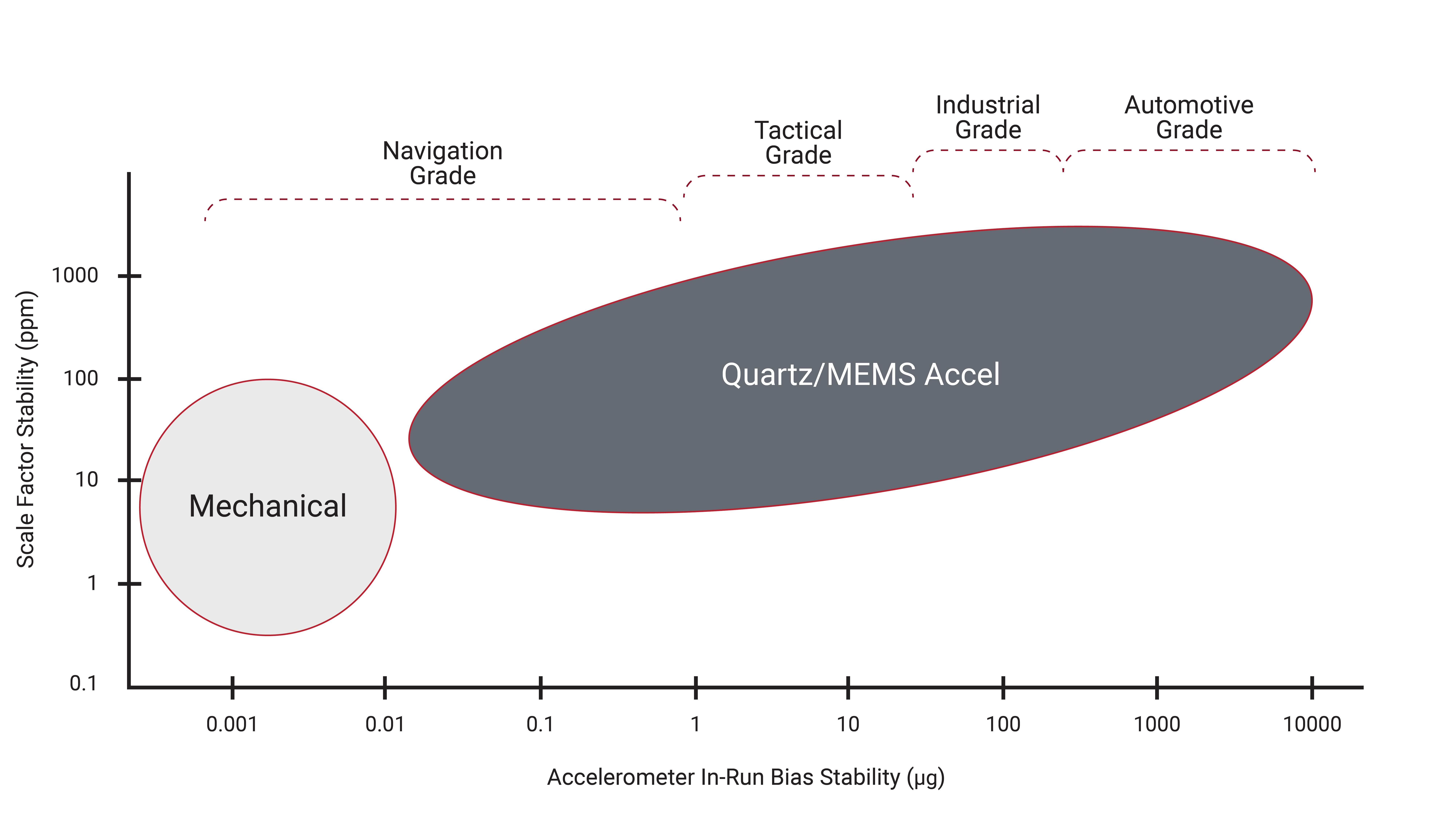
As shown in Figure 1.1, there are two main types of accelerometers that make up the different accelerometer performance categories: mechanical accelerometers and quartz/MEMS accelerometers. Quartz and MEMS accelerometers typically have an in-run bias stability ranging anywhere from 1000 µg down to 1 µg and span all four of the performance categories, while mechanical accelerometers can reach in-run bias stabilities less than 1 µg but are generally only used in navigation grade applications due to their large size and cost.
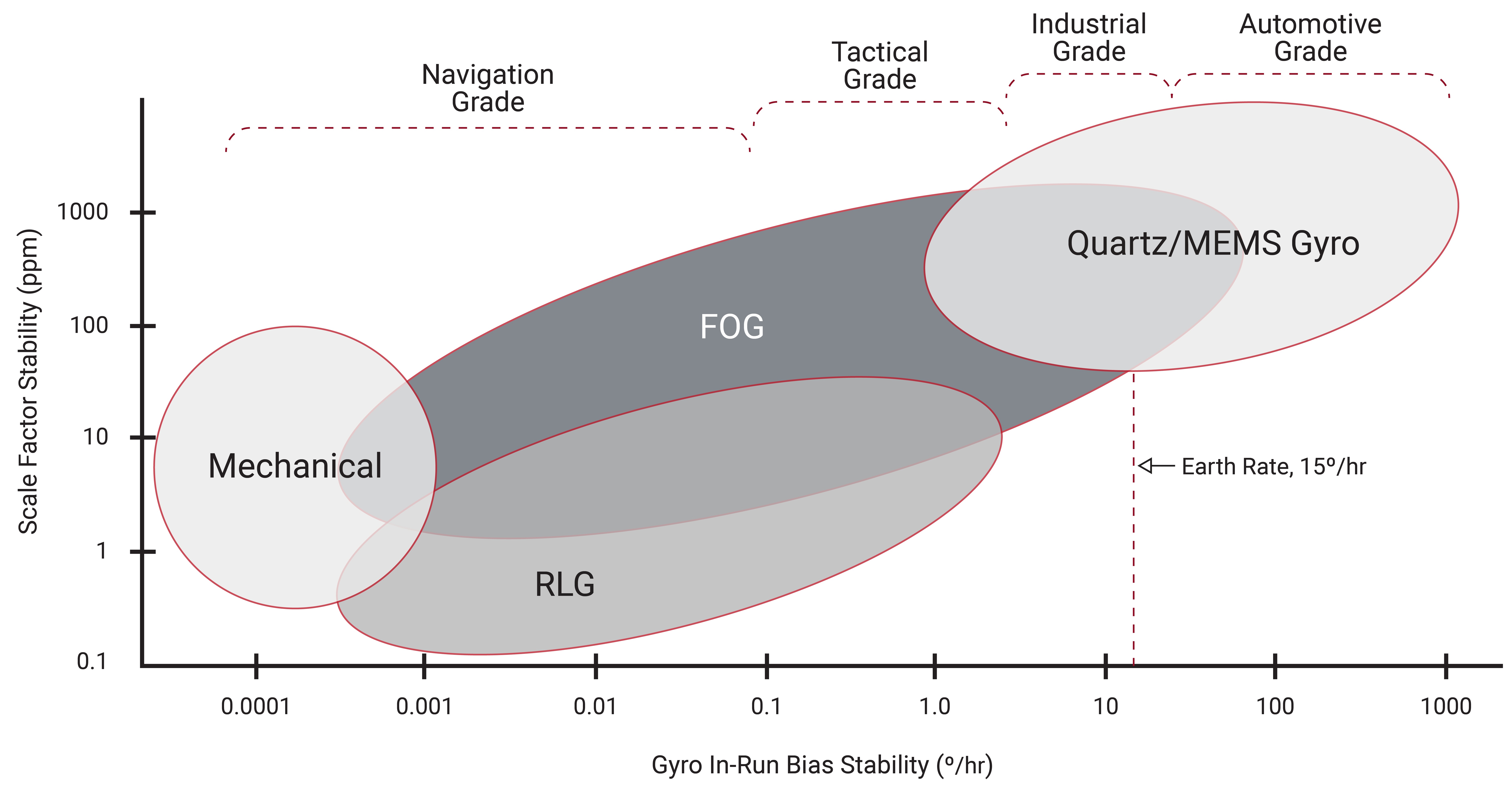
There are many different types of gyroscopes available on the market, which range over various levels of performance and include mechanical gyroscopes, fiber-optic gyroscopes (FOGs), ring laser gyroscopes (RLGs), and quartz/MEMS gyroscopes as illustrated in Figure 1.2. Quartz and MEMS gyroscopes are typically used in the consumer grade, industrial grade, and tactical grade markets, while fiber-optic gyroscopes span all four of the performance categories. Ring laser gyroscopes typically consist of in-run bias stabilities ranging anywhere from 1°/hour down to less than 0.001°/hour, encompassing the tactical and navigation grades. Mechanical gyroscopes make up the highest performing gyroscopes available on the market and can reach in-run bias stabilities of less than 0.0001°/hour.
Accelerometers and gyroscopes can be used as individual inertial sensors, but most applications combine these sensors together into an inertial system. When a gyroscope is used in conjunction with an accelerometer, the performance of the gyroscope typically has the greater impact on the inertial navigation performance. Due to this, the gyroscope in-run bias stability is often used as a short-hand measure of inertial system quality. Table 1.1 provides the typical gyroscope in-run bias stabilities associated with each of the different inertial sensor performance grades.
| GRADE | COST | GYRO IN-RUN BIAS STABILITY | GNSS-DENIED NAVIGATION TIME | APPLICATIONS |
|---|---|---|---|---|
| Consumer | <\$10 | -- | -- | Smartphones |
| Industrial | \$100-\$1000 | <10°/hour | <1 min | UAVs |
| Tactical | \$5,000-\$50,000 | <1°/hour | <10 min | Smart Munitions |
| Navigation | >\$100,000 | <0.1°/hour | Several hours | Military |
When determining which grade of inertial sensor is the best fit for a specific application, it is important to know what type of accuracy is required as well as the budget constraints for the project. As the performance grades of the inertial sensors increase, so does their associated cost, as shown in Table 1.1. The low cost of consumer grade inertial sensors makes them ideal for use in smartphones and tablets. Navigation grade inertial sensors, on the other hand, have a much higher accuracy, but also have a much higher cost making them practical only in the most mission-critical applications.
Inertial Sensing Nomenclature
As the inertial sensor market has grown, the use of inertial sensors and consequently the different nomenclature used to describe inertial sensors has expanded as well. The plethora of technical terms and acronyms used in company literature and information available on the internet makes it difficult to determine which combination of inertial sensors is best suited for a specific application. Furthermore, many of these terms are used interchangeably, so it is important to understand the components that make up each of these systems as well as the calculated navigation outputs that each provides. Some of the more common inertial sensing nomenclature is described in Table 1.2, note that the sensors listed in parentheses may or may not be included in the inertial system.
| ACRONYM | NAME | SENSORS | NAVIGATION OUTPUTS |
|---|---|---|---|
| IMU | Inertial Measurement Unit | Gyro + Accel + (Mag) | None |
| IRU | Inertial Reference Unit | Gyro + Accel + (Mag) | None |
| INS | Inertial Navigation System | Gyro + Accel + (Mag) | Position, Velocity, Attitude |
| VRU | Vertical Reference Unit | Gyro + Accel | Pitch, Roll & Heave |
| AHRS | Attitude Heading Reference System | Gyro + Accel + Mag | Attitude |
| MRU | Motion Reference Unit | Gyro + Accel + (Mag) | Varies |
When referring to the inertial systems listed in Table 1.2, it is common to describe them based on the number of total axes that the system measures. An individual inertial sensor can only sense a measurement along or about a single axis. To provide a three-dimensional solution, three individual inertial sensors must be mounted together into an orthogonal cluster known as a triad. This set of inertial sensors mounted in a triad is commonly referred to as a 3-axis inertial sensor, as the sensor is able to provide one measurement along each of the three axes. Similarly, an inertial system consisting of a 3-axis accelerometer and a 3-axis gyroscope is referred to as a 6-axis system as it provides two different measurements along each of the three axes for a total of six measurements. Table 1.3 defines a few of the more common sensor combinations.
| NUMBER OF AXES | ACCELEROMETER | GYROSCOPE | MAGNETOMETER | BAROMETER |
|---|---|---|---|---|
| 6-Axis | 3-Axis | 3-Axis | -- | -- |
| 9-Axis | 3-Axis | 3-Axis | 3-Axis | -- |
| 10-Axis | 3-Axis | 3-Axis | 3-Axis | 1-Axis |
