Educational Material
1.8 GNSS Compass/INS (Dual GNSS/INS)
A GNSS Compass/INS, or Dual GNSS/INS, consists of two onboard GNSS receivers, forming a GNSS compass, and an onboard inertial navigation system (INS). The position and velocity measurements from the onboard GNSS modules are coupled with the inertial sensor measurements to provide estimates of a system's position, velocity, and attitude with higher accuracy and better dynamic performance than a standalone GNSS or INS system can provide.
System Contributions
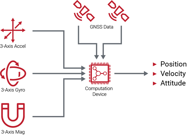
Typically, a GNSS Compass/INS includes a 3-axis gyroscope, a 3-axis accelerometer, two GNSS receivers, and sometimes a 3-axis magnetometer to determine an estimate of the system's position, velocity, and attitude. Each of these devices provide similar contributions to a GNSS Compass/INS that they provide to a GNSS/INS system, which can be found in Section 1.7. A GNSS Compass/INS also contains an additional feature that utilizes the two separate onboard GNSS receivers to accurately estimate the system's heading: the powerful technique known as GNSS compassing.
GNSS Compass
The GNSS compass technique uses a form of the real-time kinematic positioning (RTK) technique known as moving-baseline RTK to determine a system's heading. Traditional RTK is a precise positioning method that compares the carrier phase measurements between two antennas, a reference antenna which is typically stationary at a known location and a rover antenna that is able to move freely. This comparison of the carrier phase measurements allows RTK to determine a relative position between the two antennas to very high accuracy. For more information on carrier phase measurements and traditional RTK, see Section 1.2 and Section 1.5. Moving-baseline RTK is a particular form of traditional RTK that allows both the reference antenna and the rover antenna to move freely. A GNSS compass is unique in that the two antennas are rigidly mounted with respect to each other with a fixed distance between the two antennas, known as the compass baseline. Ideally, both antennas should also be mounted in the same orientation, as the RF phase center of an antenna is not always located in the center of the antenna. The RF phase center of an antenna is the point where the antenna can receive signals, so aligning the two antennas in the same orientation ensures an accurate compass baseline measurement.
Similar to traditional RTK, moving-baseline RTK compares the carrier phase measurements from the GNSS signals between two antennas, allowing the GNSS Compass to determine the relative positioning of the two antennas in an inertial frame of reference to millimeter-level accuracy. If the position of the two antennas relative to each other is also known in the sensor's frame of reference, then the heading angle can be calculated in real-time with a high degree of accuracy. It is important to note that this heading measurement is derived directly from differencing the two GNSS receiver measurements at a single point in time, it does not require motion as is the case for dynamic alignment.
System Fusion
A GNSS Compass/INS operates similar to a GNSS/INS system, though it differs from a single-antenna system in that is has the capability to accurately estimate the heading in both static and dynamic conditions using the GNSS compass. This allows the system to accurately estimate the heading with respect to true North, without any reliance on magnetic sensors. In practice, a GNSS Compass/INS relies on dynamic alignment when available, but instead of falling back on the magnetic compass like a single-antenna GNSS/INS, it falls back on the GNSS compass solution. The accuracy of the heading estimate derived from the GNSS compass is dependent on the quality of the GNSS signal, the baseline distance between the two antennas, and the accuracy of this baseline distance measurement. As shown in Equation \ref{eq:compe}, the error in the heading estimate, $\theta_{err}$, is inversely proportional to the antenna baseline ${L}$. Due to this, it is important that the compass baseline between the two antennas is measured as accurately as possible.
\begin{equation} \label{eq:compe} \theta_{err} = \frac{P_{err}}{L}\end{equation}
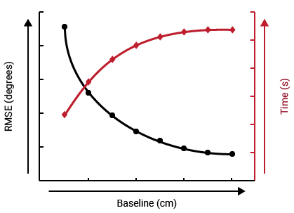
Longer baseline distances provide higher accuracy GNSS compass heading estimates as the position error from the moving-baseline RTK, $P_{err}$ , remains nearly constant over varying baseline distances. However, longer baseline distances do increase the start-up time required for the GNSS compass to lock onto the correct heading estimate.
The relative positioning from the moving-baseline RTK can also provide the GNSS Compass with a measurement of the pitch and roll angles. However, because the vertical channel of GNSS is half as accurate as the horizontal channel, these measurements typically are not able to provide accurate estimates of pitch and roll and are consequently not commonly used in a GNSS Compass/INS.
Challenges of GNSS Compass
A GNSS Compass/INS system experiences all of the same challenges as a GNSS-aided INS system, which can be found in Section 1.7. However, the addition of the GNSS compass requires a GNSS Compass/INS system to have much better satellite signal conditions than a single antenna system. Due to this, there are a few added challenges that must be overcome when using a GNSS Compass INS including:
- Maintaining a direct line-of-sight to the satellites
- Observing six common satellites between the two antennas
- Reducing multipath interference
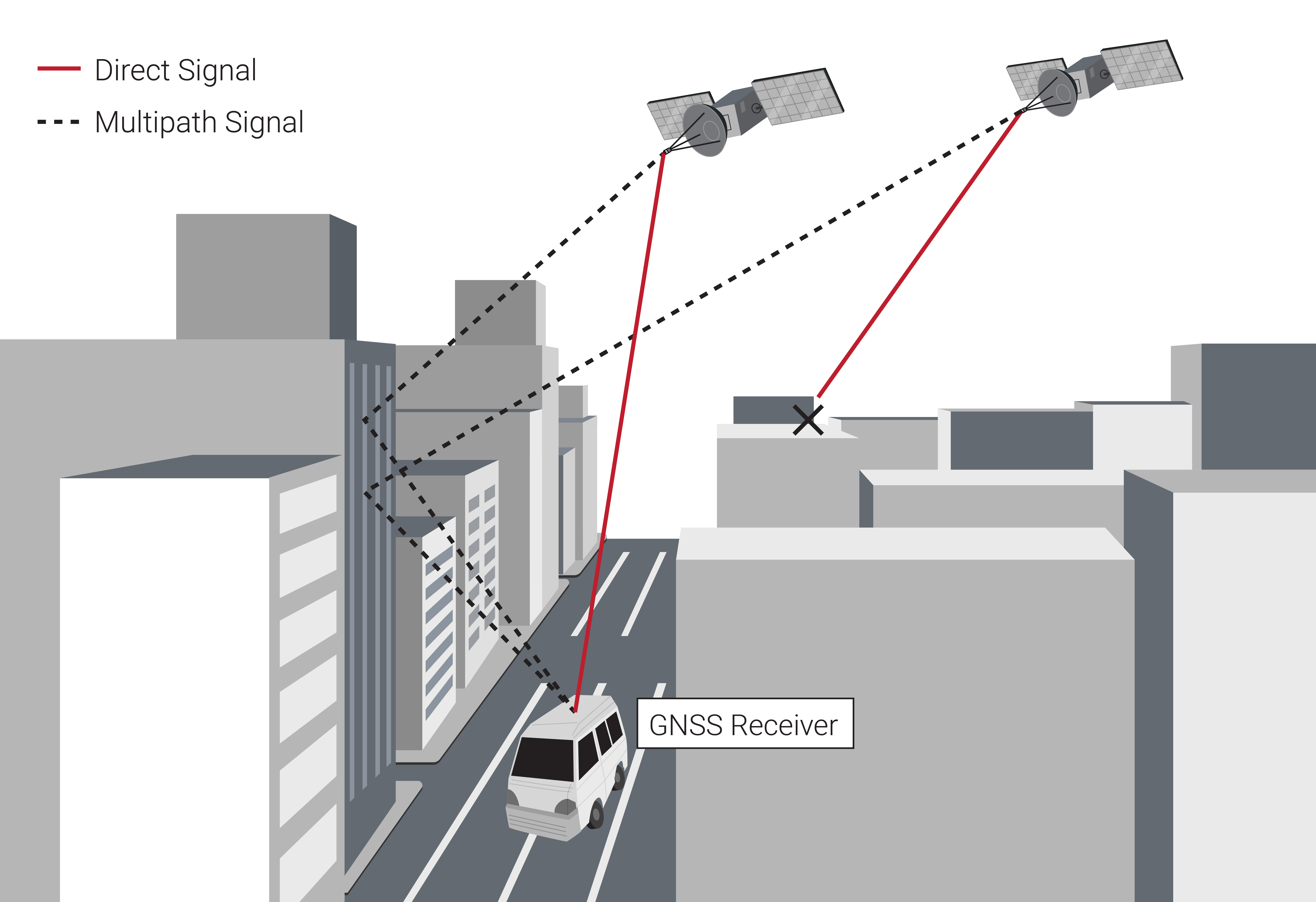
A GNSS Compass/INS system requires that both GNSS antennas are mounted with a clear view of the sky, allowing the antennas to have a direct line-of-sight to the satellites. In addition, in order for the GNSS compass to estimate the heading using moving-baseline RTK, the two antennas must observe at least six of the same satellites. If there are any type of obstructions, such as foliage or buildings, that prevent the antennas from seeing six of the same satellites, the GNSS compass is unable to estimate the system's heading. The GNSS Compass/INS is also more sensitive to multipath interference than a single antenna GNSS/INS system. Multipath interference occurs when GNSS satellite signals reflect off of solid objects such as buildings and terrain, resulting in the signal taking multiple paths to reach the antenna, as shown in Figure 1.26. These reflected signals are delayed as compared to direct line-of-sight signals, causing errors in the carrier phase measurements, which are used in the GNSS compass. The most common cause of multipath interference is due to signals reflecting up from the ground to the bottom of the GNSS antennas. To mitigate this, it is recommended that ground planes be placed underneath the antennas to block these signals from reflecting up from the ground.