
APPLICATIONS
Lidar Mapping
Light Detection and Ranging (LiDAR) is a measurement technique that uses light emitted from a sensor to measure the range to a target object. In very simple terms the sensor emits a light pulse and then measures the time taken to receive the reflected pulse in order to estimate the range of the target object, given the constant of the speed of light. Modern LiDAR sensors have multiple lasers or channels, 8 to 128, that are able to produce up to 2.2 million points per second. The LiDAR unit scans from side to side, with some having a full 360 degree horizontal Field of View (FOV), which creates a very dense point cloud that represents the surrounding area.
LiDAR sensors are able to achieve range accuracy of 0.5 to 10mm relative to the sensor and a mapping accuracy of up to 1cm horizontal (x, y) and 2cm vertical (z). This makes them particularly useful as a remote sensing tool for mobile mapping. Additionally, LiDAR sensors are able to collect multiple returns from a single light pulse. This is because as the light pulses travel from the sensor they may encounter several objects that will reflect the pulse such as leaves and branches of a tree canopy. LiDAR sensors are able to record this information to provide a detailed understanding of not only the tree canopy but also the underlying structure. Using these multiple returns LiDAR mapping is able to produce both a:
- Digital Elevation Model (DEM), which is a topology model of the earth’s surface, with natural (trees and other vegetation) and built (buildings, bridges, communication and power lines) objects removed, and a
- Digital Surface Model (DSM), which includes all natural and built features, e.g. communications lines, bridges, vegetation etc.
DATA REQUIREMENTS
IMU Data
Angular Rate
Attitude Data
Yaw, Pitch, Roll
Navigation Data
Position, Velocity
DOWNLOAD OUR FREE LIDAR MAPPING APPLICATION NOTE
RECOMMENDED PRODUCTS
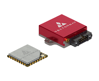
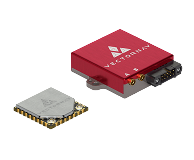
VN-200
GNSS / INS
VN-210
GNSS / INS
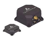
VN-300
DUAL GNSS / INS

VN-310
DUAL GNSS / INS