EO/IR SURVEILLANCE

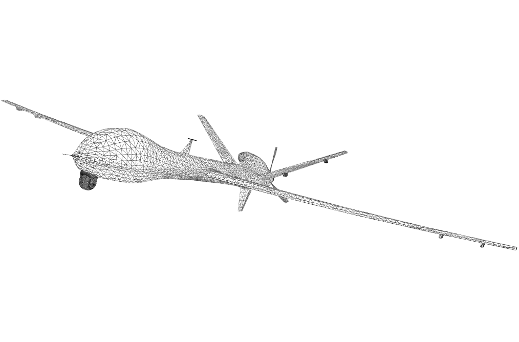
UAV EO IR Surveillance

INTRODUCTION

Gimballed systems are one of the most common payloads on everything from UAVs to marine vessels, enabling pointing of that payload independent of the vehicle attitude. That independent motion also allows for stabilization, decoupling the high-frequency motion and vibrations of the platform or vehicle from those of the payload. For military, law enforcement, search and rescue and humanitarian disaster response, real-time intelligence, surveillance and reconnaissance (ISR) information is critical to operations, aircraft can be fitted with a sophisticated sensor suite consisting of Electro Optical (EO) and InfraRed (IR) instruments, or other spectral imaging sensors on a stabilized platform to capture aerial imagery data over a broad area.

Most systems utilize two-axis gimbals to provide full pointing control. Two-axis gimbals are sometimes referred to as az-el stages or pan-tilt units, which can broadly be broken down into three distinct components.

  • The base, which is fixed to whatever platform or vehicle is carrying the gimbal,
  • The outer axis, which moves relative to the base, typically the pan or azimuth axis, and
  • The inner axis, which moves relative to the outer axis and provides tilt or elevation control.

The camera, antenna, or other payload are mounted to the inner axis.

Summary

Data Requirements

IMU Data: Angular Rate
Attitude Data: Yaw, Pitch, Roll
Navigation Data: Position, Velocity

Recommended Products
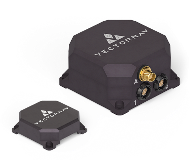
GNSS / INS
VN-210
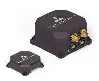
Dual GNSS / INS
VN-310
Gimal Wireframe (1)
FIgure 1: Two-Axis Gimbal
Gimbal_Simplified_Fig (2)
Figure 2: EX-EL/Pan-tilt

DOWNLOAD THE GIMBAL STABILIZATION AND POINTING APPLICATION NOTE

To learn more about the three approaches please download our Gimbal Stabilization and Pointing Application Note.

SENSOR CATEGORY SELECTION

For most gimbal pointing applications, including geo-referencing, the gimbal control system requires position data, which precludes a pure IMU or AHRS solution and requires a GNSS-aided option.

In manned systems, the vehicle's onboard navigation system is a safety-critical component and interfacing with it can be onerous. In unmanned systems, the autopilot or equivalent can generally maintain vehicle control with a lower-precision navigation system than required for accurate pointing of most payloads. And in both cases, flexing of the vehicle introduces errors since the platform's INS is typically mounted near the center of mass of the vehicle and not co-located with the gimbal. Therefore it is best that gimballed payloads incorporate their own position and attitude sensing in most applications.

A GNSS/INS provides accurate heading under dynamic conditions, where the horizontal accelerations measured independently by the accelerometer and the GNSS can be correlated to track a high-accuracy heading output - a process known as dynamic alignment. This is well suited to fixed wing applications, however for static or low-dynamic applications such as helicopters, rotorcraft or marine vessels a dual-antenna GNSS/INS is a preferred solution as it incorporates and GNSS Compass to provide high accuracy heading data independent of magnetometers.

GNSS/INS SOLUTIONS

VN-200 Rugged & VN-210

DUAL GNSS/INS SOLUTIONS

VN-300 Rugged & VN-310

Geolocation

For ISR applications it may be necessary to map a point or a feature on an image to a global coordinate frame. The estimated point on the groundimage10can be found by taking the offset of the feature in the camera (image1,image2,image3) and rotating it to an NED coordinate frame using an estimated coordinate frame transformation matrix image6(the attitude of the camera relative to NED) and multiplying it by the slant range (L), which is then added to the position of the aircraft image8 as shown in the following equation:

image5

One thing that can’t be directly measured by either the EO/IR system or the GNSS/INS is the slant range (L). One method to solve for the correct value is to find a slant range such that the pointing solution falls on the surface of a Digital Elevation Model or map (DEM), which is the approach used in the example below.

ISR applications, understanding the slant range between gimbal and point on ground.
Figure 3: Slant range between gimbal and point on ground.

Error Budget

Using heading and position data we are able to georeference a point. However we need to consider the contribution of uncertainties/errors in the attitude and position estimates to the accuracy of the georeferencing solution. The error budget determines the contribution of all sources - each sensor has an inherent margin of accuracy - that affect the acquired data quality, to check if the degree of uncertainty in the measurement solution meets the minimum required specifications.

For our ISR application we need to consider contributions from:

  • GNSS/INS attitude and position uncertainties
  • Misalignment
  • Timing errors
Contribution from the GNSS/INS attitude and position errors relatively easily mapped to the flat DEM. 

The more challenging items to address are the two sources of misalignment errors. Misalignment error is an orthogonality error caused by the measuring axis being misaligned. In our case of a gimballed georeferencing application this is a misalignment between the camera and the navigation system (GNSS/INS). This misalignment can be broken down into its various sources:

  • GNSS/INS misalignment
  • Gimbal and encoder misalignment
In order to compensate for GNSS/INS misalignment errors, the system should be calibrated to determine the fixed misalignment offset by comparing it to an independent source of truth. Gimbal and encoder misalignment are a result of the flawed assumption that all axes are perfectly perpendicular, unfortunately this is not the case due to manufacturing tolerances. Additionally encoders are limited in resolution which leads to quantization errors.

A quick example

A plane traveling at 50m/s due North at a height of 1000m, the camera is pointed at 60° directly in front of the vehicle with a theoretical slant range of 2000m.

In a flat DEM the error budget from horizontal GNSS/INS uncertainty directly comes from the GNSS horizontal position uncertainty in an NED coordinate frame. For standard GNSS this gives an error of 2m in the North and East axis. The contribution from the GNSS altitude uncertainty gets projected onto the DEM as a function of the gimbal tilt angle as shown in the equation below. The position error contribution can be reduced to centimeter level by using RTK.

Understand how GNSS altitude uncertainty and gimbal tilt angle contribute to direct georeferencing errors.

GNSS/INS roll/yaw uncertainties produce errors perpendicular to the slant range which is parallel to the DEM. Pitch uncertainties produce errors perpendicular to which need to be projected as a function of α.

The error budget contribution from time is caused by the time delay in the measurements. Since we assume that the gimbal remains fixed the error contributed by the timing is in the direction of the velocity of the vehicle, which for this example is due North on the NED axis.

The graph below illustrates the total error budget for our application.

See how pitch, horizontal position errors and vertical position errors contribute to the error budget for direct georeferencing applications

Figure 4: Pitch, horizontal position errors and vertical position errors.


Total error budget for a flat DEM at a height of 1000m with the gimbal pointed at 60 degrees.

Figure 5: Total error budget for a flat DEM at a height of 1000m with the gimbal pointed at 60 degrees

ISR GIMBAL APPLICATION NOTE

To learn more about sensor selection, implementation and determining your error budget for ISR applications take a look at our in-depth application note.

CONCLUSION

Intelligence, Surveillance and Reconnaissance (ISR) applications can be used for military, law enforcement, search and rescue, and humanitarian disaster response. For many of these applications an EO/IR camera is mounted on a gimbal to find and geo-reference points of interest. Gimbals often need their own navigation system as the navigation system of the aircraft may not be accurate enough for gimbal pointing or, in some cases, the aircraft’s navigation system may be mission critical and thus inaccessible.

UAV_Factory

VECTORNAV SUPPORT LIBRARY

Everything you need to know about inertial navigation.

Contact Us

I am looking for: *
Opt In