
APPLICATIONS
Aerial Photogrammetry
Photogrammetry is the estimation of the geometric and semantic properties of objects based on images or observations from similar sensors. What this translates to is that photogrammetry is the process of taking measurements of distances, areas, and volumes of an environment based on photographs taken from various vantage points. These measurements can then be used to produce an orthophoto map (Orthomosaic), Digital Surface Model, or 3D point cloud.
Legislative changes and advancements in UAV technology, size and weight reduction in sensors, and advances in compact data storage/transmission has seen significant growth in UAV aerial photogrammetry. Aerial photogrammetry is expanding into new applications and end uses that were previously too costly or impractical. Professional photogrammetry can produce outputs with horizontal (x,y) accuracies in the range of 1 cm (0.4 in) and elevation (z) accuracies of 2 to 3 cm (0.8 to 1.2 in), which enables precise volumetric analysis. In this section we are going to focus on photogrammetry and the advantages of using a GNSS/INS to provide more efficient and cost effective aerial mapping.
DATA REQUIREMENTS
IMU Data
Angular Rate
Attitude Data
Yaw, Pitch, Roll
Navigation Data
Position, Velocity
DOWNLOAD OUR FREE AERIAL PHOTOGRAMMETRY APPLICATION NOTE
RECOMMENDED PRODUCTS
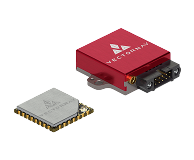
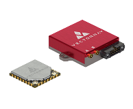
VN-200
GNSS / INS
VN-210
GNSS / INS
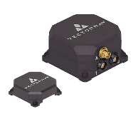
VN-300
DUAL GNSS / INS

VN-310
DUAL GNSS / INS