.png?sfvrsn=bbc774aa_0 "SATCOM on the Move")
APPLICATIONS
SATCOM On The Move (SOTM)
Today there is greater and greater demand for communication anywhere at anytime, in commercial multi-media requirements and military intelligence, surveillance and reconnaissance communication requirements. The need to maintain persistent mobile communications regardless of location in the world has driven significant growth in Satellite Communications (SATCOM) and particularly for SATCOM on-the-move (SOTM) products and service offerings.
SATCOM is the use of a network of geostationary satellites for the relay of radio communications between a transmitter and receiver located at two different points on the earth. The key challenge for any SATCOM system is maintaining the line-of-sight (LOS) connection with the target satellite. Fortunately, there is no need to track the target satellite, as its orbit is in sync with the earth's rotation and appears fixed in the sky. However, to maximize the number of satellites in geostationary orbit, these satellites are placed very close together with adjacent satellites typically located within a few degrees of each other. Due to this, high-accuracy pointing is required from a SATCOM terminal to send and receive large amounts of data and prevent interference on neighboring satellites. In fact, in order to maximize the transmission power of the antenna and remain within regulatory requirements as stated in the FCC Vehicle-Mounted Earth Station (VMES) rules, the antenna pointing error must be less than 0.2° (3𝞂), as illustrated in Figure 1.
DATA REQUIREMENTS
IMU
Angular Rate
Attitude
Yaw, Pitch, Roll
Navigation
Position, Velocity
DOWNLOAD OUR FREE GIMBAL STABILIZATION & POINTING APPLICATION NOTE
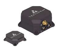
RECOMMENDED PRODUCTS

VN-200
GNSS / INS
VN-210
GNSS / INS

VN-300
DUAL GNSS / INS

VN-310
DUAL GNSS / INS