Educational Material
1.6 Attitude & Heading Reference System (AHRS)
An attitude and heading reference system (AHRS) uses an inertial measurement unit (IMU) consisting of microelectromechanical system (MEMS) inertial sensors to measure the angular rate, acceleration, and Earth's magnetic field. These measurements can then be used to derive an estimate of the object's attitude.
System Contributions
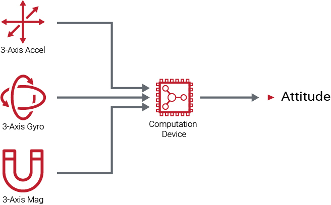
An AHRS typically includes a 3-axis gyroscope, a 3-axis accelerometer, and a 3-axis magnetometer to determine an estimate of a system's orientation. Each of these sensors contribute different measurements to the combined system and each exhibit unique limitations.
Gyroscope
A gyroscope provides an AHRS with a measurement of the system's angular rate. These angular rate measurements are then integrated to determine an estimate of the system's attitude. However, in order to determine the current attitude, the initial attitude of the system must also be known. Over time, this calculated attitude drifts unboundedly from the true attitude of the system due to the inherent noise and bias properties of the gyroscope itself.
Accelerometer
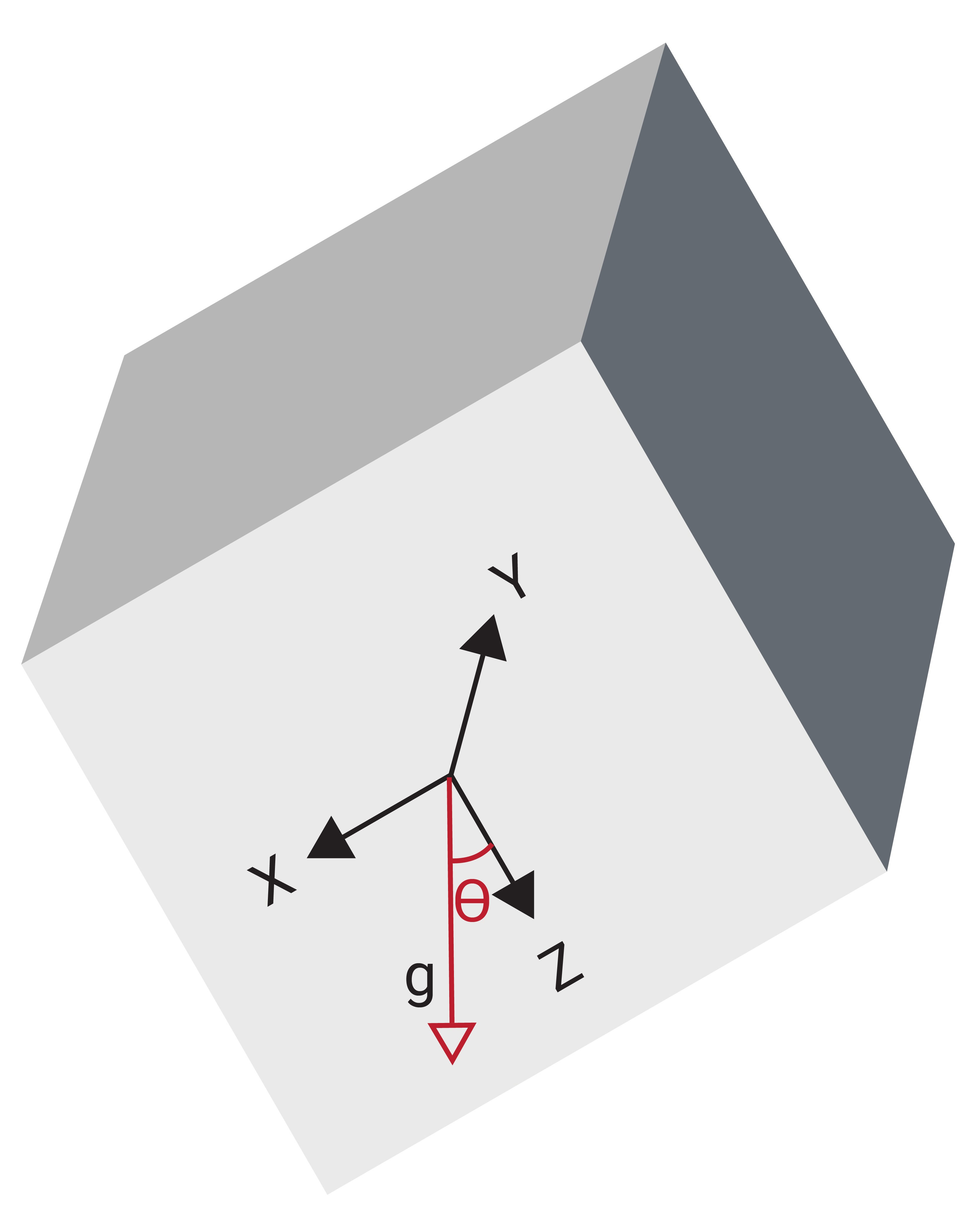
An accelerometer supplies an AHRS with a measure of the system's acceleration and is assumed to be measuring gravity alone. This assumption allows the accelerometer to calculate the pitch and roll angles from the direction of the gravity vector, as illustrated in Figure 1.15. However, any biases or other errors in the accelerometer measurements cause errors in the calculation of the pitch and roll angles. In addition, since the accelerometer is assumed to be measuring gravity alone, any added dynamic motion also causes an error in the calculation of the system's pitch & roll.
Magnetometer
Since the accelerometer can only measure pitch & roll, a magnetometer provides an AHRS with a measurement of yaw by comparing the measurement of the magnetic field surrounding the system to Earth's magnetic field, just like a traditional magnetic compass. In most AHRS units, the magnetometer measurements have no impact on the pitch and roll angle estimates.
While seemingly straightforward, using a magnetometer to accurately estimate the heading can actually prove to be quite challenging. Earth's magnetic field is weak, so large metal structures, high power cables, or any other magnetic disturbances can distort Earth's magnetic field and cause errors in the estimated heading angle. Disturbances caused by objects to which the AHRS is fixed (eg. the vehicle) can be compensated using a calibration known as hard & soft iron (HSI) calibration, but only when those disturbances do not vary over time. Advanced filtering techniques can be used to mitigate the impact of external disturbances in the environment, but their effectiveness varies by manufacturer and application.
Additionally, the magnetic North Pole of the earth is not in the same location as True North or the geographic North Pole of the earth. If the heading angle with respect to True North is desired, the declination angle between these two poles must be factored into the heading determination.
System Fusion
In an AHRS, the measurements from the gyroscope, accelerometer, and magnetometer are combined to provide an estimate of a system's orientation, often using a Kalman filter. This estimation technique uses these raw measurements to derive an optimized estimate of the attitude, given the assumptions outlined for each individual sensor. The Kalman filter estimates the gyro bias, or drift error of the gyroscope, in addition to the attitude. The gyro bias can then be used to compensate the raw gyroscope measurements and aid in preventing the drift of the gyroscope over time. By combining the data from each of these sensors into a Kalman filter, a drift-free, high-rate orientation solution for the system can be obtained.
Challenges of AHRS
While many of the limitations a gyroscope, accelerometer, and magnetometer face on their own can be mitigated by combining them together, there are still a few challenges that come with using a AHRS that can cause errors in the system's attitude estimate. These challenges include transient and AC disturbances on the accelerometer and magnetometer, sustained dynamic accelerations, and internal and external magnetic disturbances.
Transient or Oscillating Disturbances
Any type of transient or AC disturbance that induces an acceleration or a magnetic disturbance for a short period of time can be almost completely mitigated through proper tuning and reliance on the integrated gyro through those time constants. For industrial grade sensors, a "short" period of time corresponds to roughly a duration of <1 s, or at an oscillation faster than 1 Hz, with higher-grade sensors able to filter out longer time constants and vice versa.
Sustained Acceleration
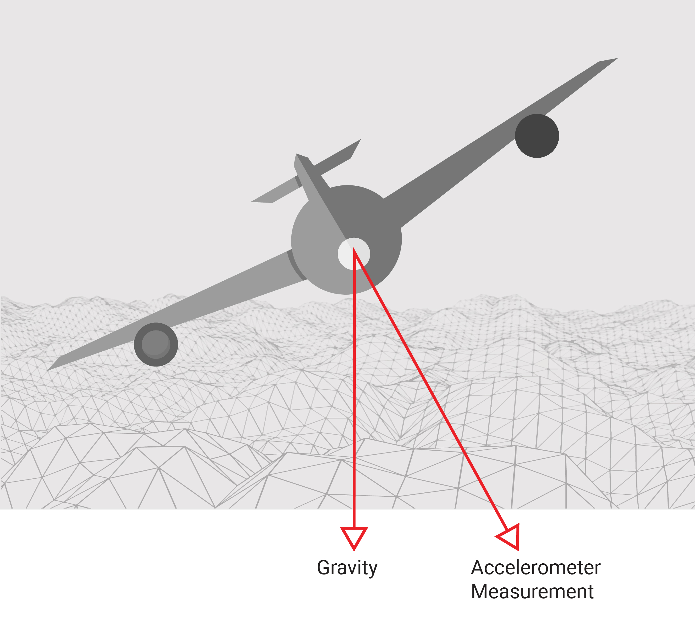
Sustained dynamic accelerations can cause a problem in the estimation of the pitch and roll angles as the assumption that the accelerometer is measuring gravity alone is constantly being violated. The most common case where this becomes a significant problem for an AHRS is when an aircraft is operating in a banked turn. When this occurs, the accelerometer measures gravity plus a long-term acceleration due to the centripetal force created by traveling along a curved path. This results in a measurement vector that acts perpendicular to the wings of the aircraft and cause the AHRS to estimate a roll angle of zero while the aircraft is in fact in a banked turn and thus has significant roll relative to the horizon, as shown in Figure 1.17.
Sustained dynamic accelerations can also be caused by the starting and stopping of a system, such as an aircraft during takeoff and landing or a vehicle at a stoplight. This type of motion causes problems in estimating the pitch angle of the system. Unfortunately, during periods of sustained dynamic accelerations the gyroscope cannot be used to ride out the motion as its inherent drift means it cannot be trusted over longer periods of time.
Finally, ballistic flight, free-fall, or orbital dynamics leave the accelerometer measuring zero, providing an AHRS filter no information regarding the orientation of the sensor. This is especially problematic for ballistic flight, when the AHRS may confuse wind-resistance for gravity.
If an AHRS receives real-time velocity measurements of the system, the sustained dynamic acceleration can be estimated and compensated for in the attitude estimation.
Magnetic Disturbances
Magnetic disturbances, which can be internal or external to the system, also pose a problem to an AHRS and cause the magnetometer to measure a biased and distorted magnetic field. Internal magnetic disturbances are a result of the magnetic signature of the system that the AHRS is rigidly attached to. They can be non-variable disturbances, such as a steel plate, or variable disturbances, such as motors or multi-rotors. External magnetic disturbances are caused by anything in the environment surrounding the system such as batteries, electronics, cars, rebar in concrete, and other ferrous materials. These magnetic disturbances lead to increased errors in the magnetometer measurements, causing errors in the estimates of the heading angle. To account for any non-variable magnetic disturbances internal to a system, a hard and soft iron (HSI) calibration can be performed on the system.
Drift in the "Drift-Free" Solution
Errors that exist in the accelerometer and magnetometer attitude solution, either due to sensor biases or to violations of the operating assumptions for each, cannot be avoided in the AHRS solution over longer periods of time. In fact, those errors can cause bounded drifting of what is otherwise considered a "drift-free" attitude solution from the AHRS.
One simple illustration of this can be revealed through a static-dynamic-static test. This test is broken up into three parts in which the system is stationary during the first part of the test, experiences dynamic motion during a short second part, and finally returns to a stationary state in the third part of the test. During the stationary periods, the system's attitude is ultimately derived from the (possibly erroneous) accelerometer and magnetometer measurements. However, during the brief dynamic section, the gyroscope measurements dominate the AHRS response.
An example of a static-dynamic-static test is shown in Figure 1.18, in which the yaw measurements are tracked as a vehicle proceeds through a turn. In this scenario, the magnetic signature of the vehicle has not been compensated using an HSI calibration, so the magnetic heading measurements are inaccurate throughout the test.
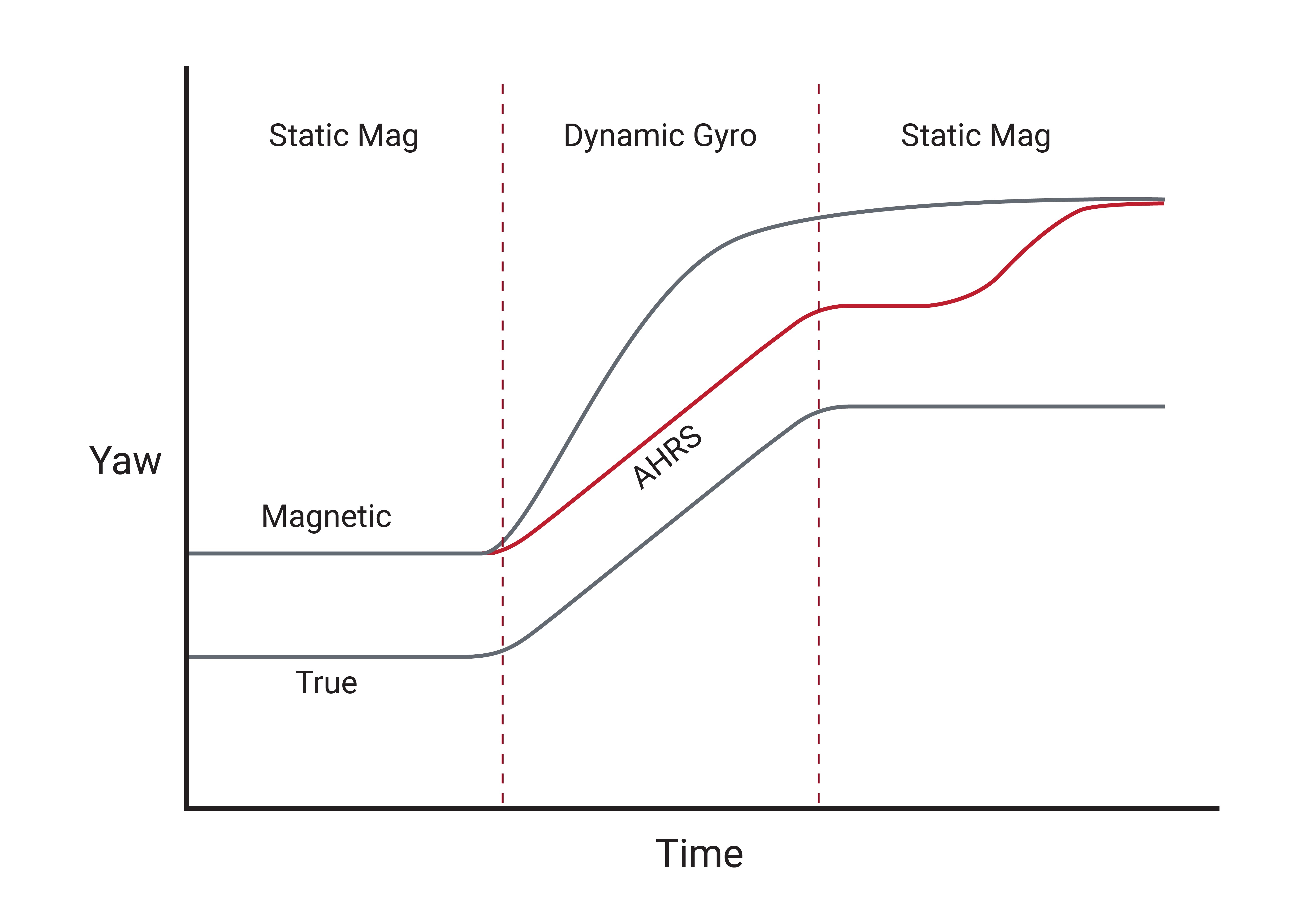
During the initial stationary section of the test, the magnetometer measurements determine the vehicle's heading. Once the vehicle begins to drive through the turn, the gyroscope accurately tracks the change in heading, even though the initial heading was in error. After the turn is completed, the vehicle returns to a stationary state. Over time, even for a well-tuned AHRS, the magnetometer exerts itself as possible drift in the gyro prevents the AHRS from continuing to trust its integrated solution. Since the magnetometer is still impacted by the magnetic signature of the vehicle, the heading reported by the AHRS drifts until it settles into the new (still-erroneous) heading reported by the magnetometer.
