Educational Material
2.1 Reference Frames
In order to describe the position, velocity, and orientation of an object of interest, the object's motion must be compared to a type of standard known as a reference frame. A reference frame is comprised of an origin that defines a position in space and three orthogonal unit vectors or axes that make up a right-handed system. These three axes are typically denoted by x-y-z or via subscripts 1-2-3. There are numerous reference frames that can be used to measure an object's motion depending on the type of application and desired results, such as a sensor frame, a body frame, an Earth-centered, Earth-fixed (ECEF) frame, or a local North-East-Down (NED) frame. Note that in most of the ensuing discussion, the location of the origin is often neglected as it is irrelevant to defining the attitude of a system.
Sensor Frame
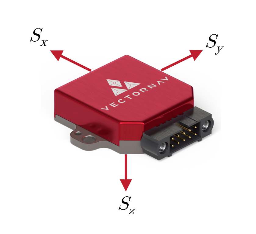
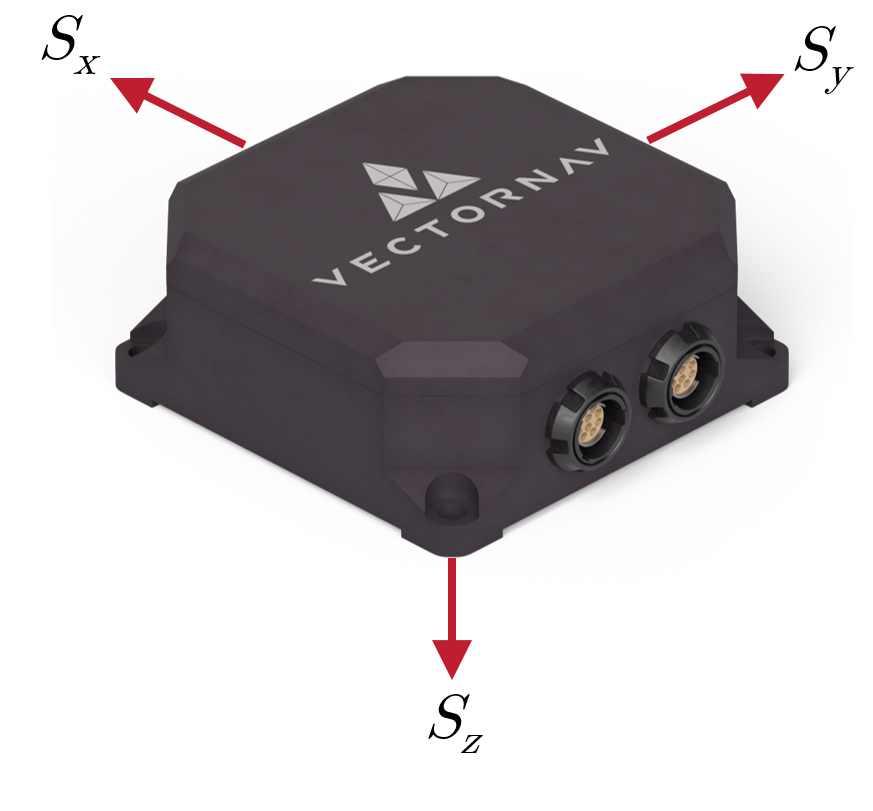
The sensor frame is a type of reference frame that is fixed to the sensor. On VectorNav sensors, the sensor frame is aligned as shown in Figure 2.1. The individual sensor element measurement axes within the instrument are aligned to the sensor frame as part of the calibration process. When reviewing a sensor's datasheet, the "Misalignment" or "Alignment Error" specification (see Section 3.1) provides an indication of how closely the measurement axes are aligned with the indicated sensor frame.
Body Frame
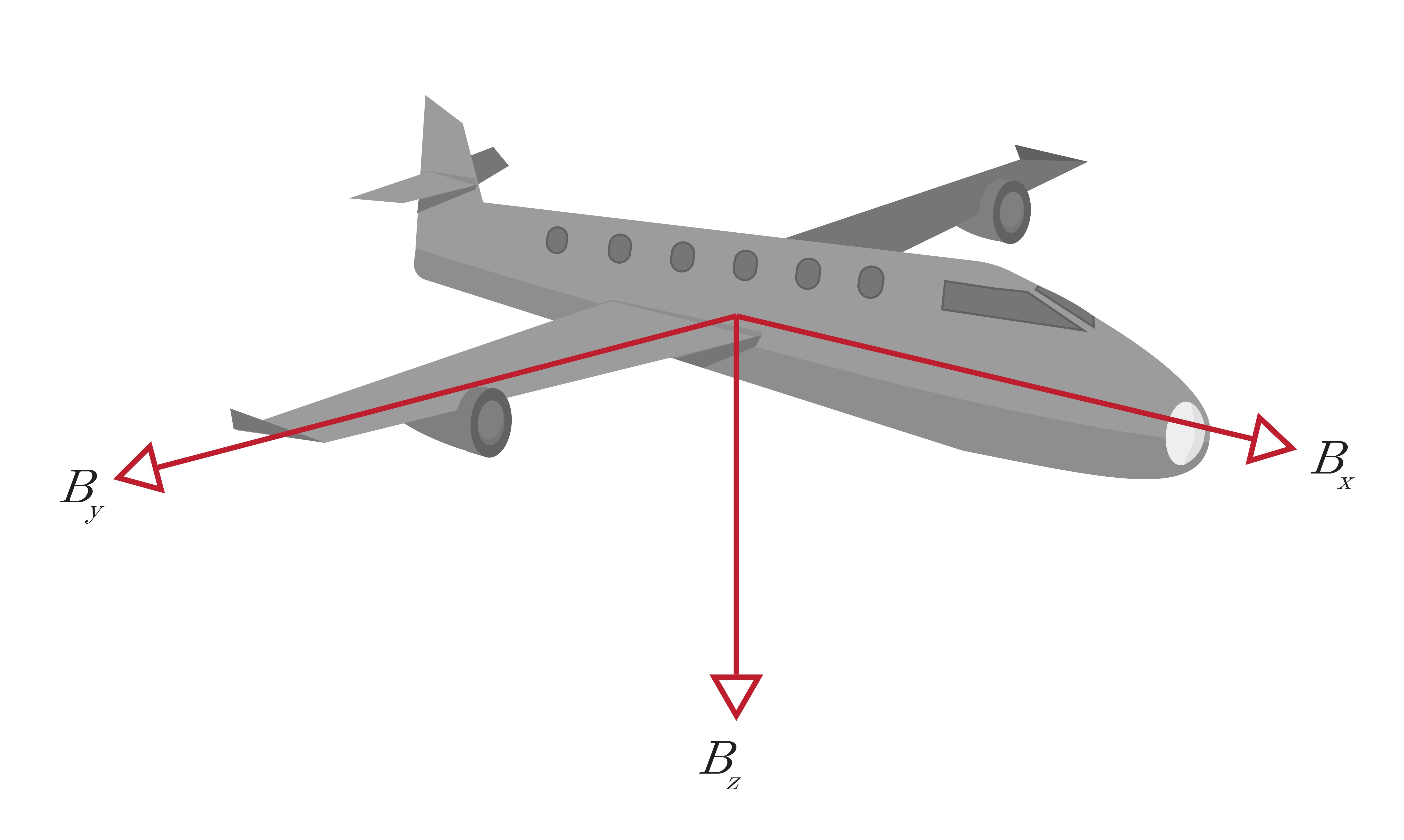
In most applications, the position, velocity, and orientation of a system are found using sensors mounted to a vehicle or platform. The platform can have its own reference frame known as the body frame, or sometimes called the vehicle frame. This type of reference frame consists of an origin that is typically placed at the platform's center of gravity and three orthogonal axes that comprise a right-handed system. These axes are usually configured to the body in such a way that the x-axis is pointing forward, the y-axis is pointing to the right, and the z-axis is pointing down as shown in Figure 2.2. In some applications, the sensor frame cannot be perfectly aligned to the body frame and will require a reference frame rotation to align the two reference frames.
Earth-Centered, Earth-Fixed (ECEF) Frame
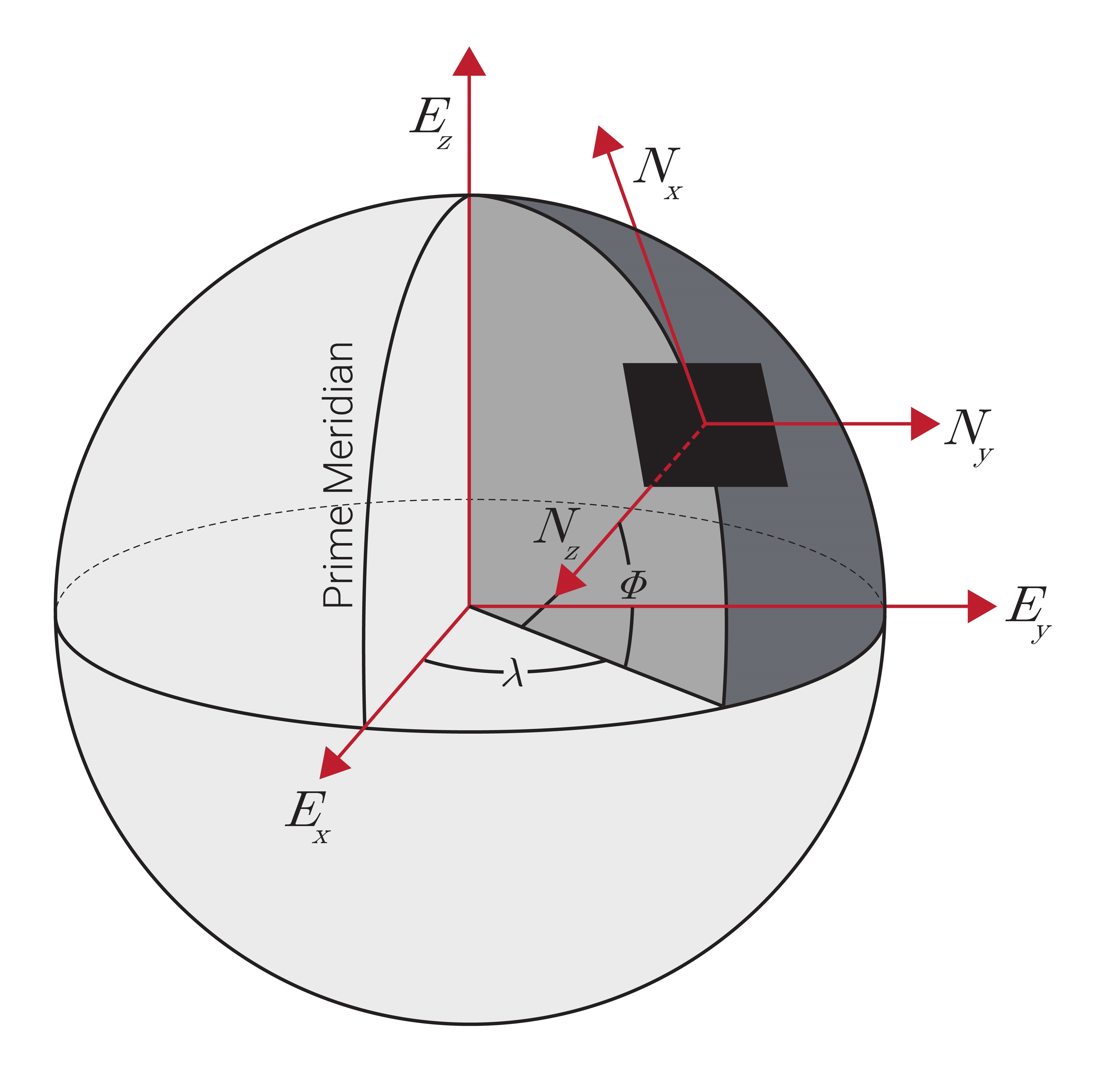
The Earth-centered, Earth-fixed (ECEF) frame is a global reference frame with its origin at the center of the earth and three orthogonal axes fixed to the earth. As shown in Figure 2.3, the $E_{z}$ axis points through the North Pole, the $E_{x}$ axis points through the intersection of the IERS Reference Meridian (IRM) and the equator, and the $E_{y}$ axis completes the right-handed system. This reference frame rotates with Earth at an angular velocity of approximately 15°/hour (360° over 24 hour).
Within the ECEF reference frame, there are two primary coordinate systems used when describing a system's position: cartesian and geodetic. The cartesian coordinate system uses the $E_x$, $E_y$, and $E_z$ axes to represent an object's position directly. The geodetic coordinate system is essentially a set of polar coordinates, but one that accounts for the first-order effect of Earth being an ellipsoid rather than a sphere, and describes an object's ECEF position in terms latitude ($\phi$), longitude ($\lambda$), and altitude ($h$).
North-East-Down (NED) Frame
The North-East-Down (NED) frame is a local reference frame that is defined by its ECEF coordinates. Often this frame is fixed to the vehicle or platform and moves with the body frame. The NED frame is defined such that the North and East axes form a plane tangent to Earth's surface at its present position, assuming a WGS84 ellipsoid model of the earth. As shown in Figure 2.3, the NED frame contains three orthogonal axes in which the $N_{x}$ axis points to True North, the $N_{z}$ axis points towards the interior of the earth and the $N_{y}$ axis completes the right-handed system pointing east.
Similar to the NED frame, there is also an East-North-Up (ENU) frame that can be placed locally on a vehicle or platform and moves around with the system. The ENU frame differs from the NED frame in the direction of the three orthogonal axes. The $N_{y}$ axis points to True North, the $N_{z}$ axis points away from the interior of the earth, and the $N_{x}$ axis completes the right-handed system pointing east.
Earth-Centered Inertial (ECI) Frame
The earth-centered inertial (ECI) frame is a global reference frame that has its origin at the center of the earth. This reference frame does not rotate with Earth and serves as an inertial reference frame for satellites orbiting Earth. Due to this, the ECI frame is used primarily in space applications.
