Educational Material
4.2 Synchronous Serial Communication
Synchronous serial communication relies on synchronized clocks between the devices on the serial bus, allowing each to sample and transmit data at known intervals. Compared to asynchronous serial communication, this eliminates the need for start and stop bits, thereby increasing throughput. One of the most common synchronous serial communication protocols is the Serial Peripheral Interface (SPI), a board-level communication standard that uses a shared clock line for synchronization and typically operates at bit rates exceeding 10 MHz.
Serial Peripheral Interface (SPI)
The serial peripheral interface (SPI) is a communication interface used to send data between multiple devices. These devices are organized into a master and slave configuration, in which the master has control over the slaves and the slaves receive instruction from the master. The most common implementation of SPI consists of a configuration in which a single device is the master, and the remainder of the devices are slaves. SPI is a synchronous communication protocol that transmits and receives information simultaneously with high data transfer rates and is designed for board-level communication over short distances.
The SPI communication interface is advantageous when needing to communicate between multiple devices. It offers a higher data transfer rate than many other types of communication interfaces and allows for data to be sent and received at the same time. However, SPI also demands more signal lines or wires than other types of communication. There is also no standard message protocol for communicating over SPI, meaning that every device could have its own convention for data message formatting.
SPI Signals
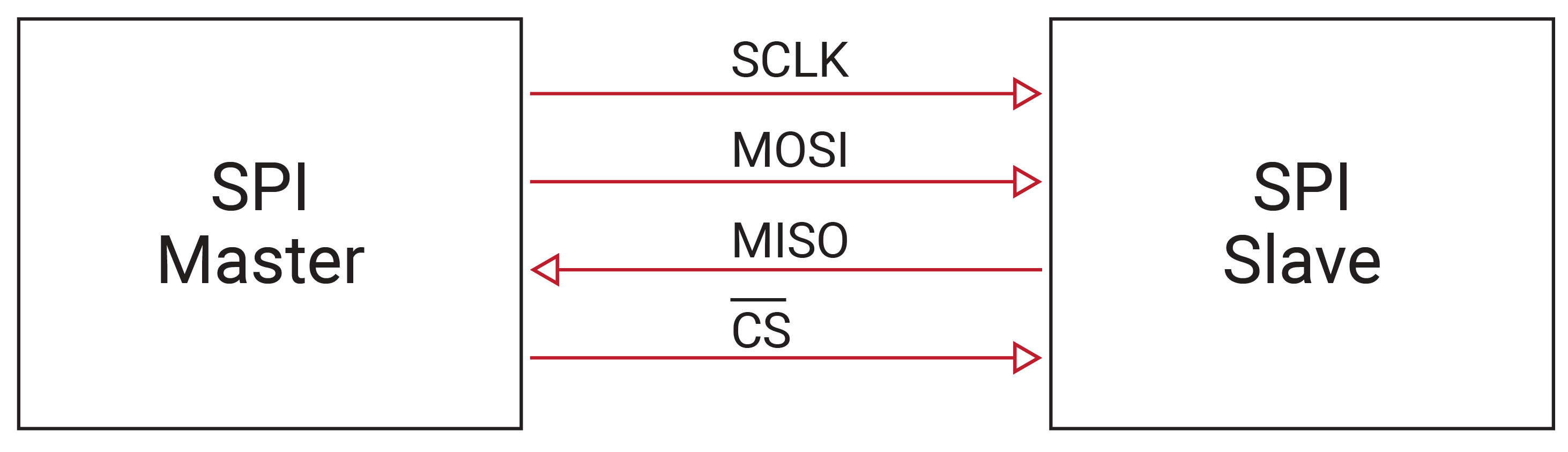
There are four signals required to implement SPI communication, as listed in Table 4.2, with all but the MISO line controlled by the master. Chip Select (CS), sometimes referred to as Slave Select (SS), is also often denoted as $\overline{\mbox{CS}}$ or $\overline{\mbox{SS}}$ because a particular chip/slave is active when that line is pulled low by the master (the line over the top indicates an inverted signal).
| SIGNAL | DESCRIPTION |
|---|---|
| MOSI | Data: Master Out - Slave In |
| MISO | Data: Master In - Slave Out |
| SCLK | Serial Clock |
| CS | Chip Select |
As shown in Figure 4.3, four wires are required to connect each of these signal lines between a single master and a single slave. These wires connect to the same signal on both devices, namely SCLK connects to SCLK, MOSI to MOSI, MISO to MISO, and CS to CS. In a multi-slave configuration, all signal lines are shared among all slaves, with the exception of the CS line which is independently controlled for each slave.
Clock Signal
The clock signal is generated by the master device to a specific frequency and is used to synchronize the data being transmitted and received between devices. This signal can be configured by the master by using two properties known as clock polarity (CPOL) and clock phase (CPHA). Clock polarity determines the polarity of the clock signal and can be configured to idle either low (0) or high (1). A clock signal that idles low has a high pulse and a rising leading edge, whereas a clock signal that idles high has a low pulse and a falling leading edge as illustrated in Figure 4.4.
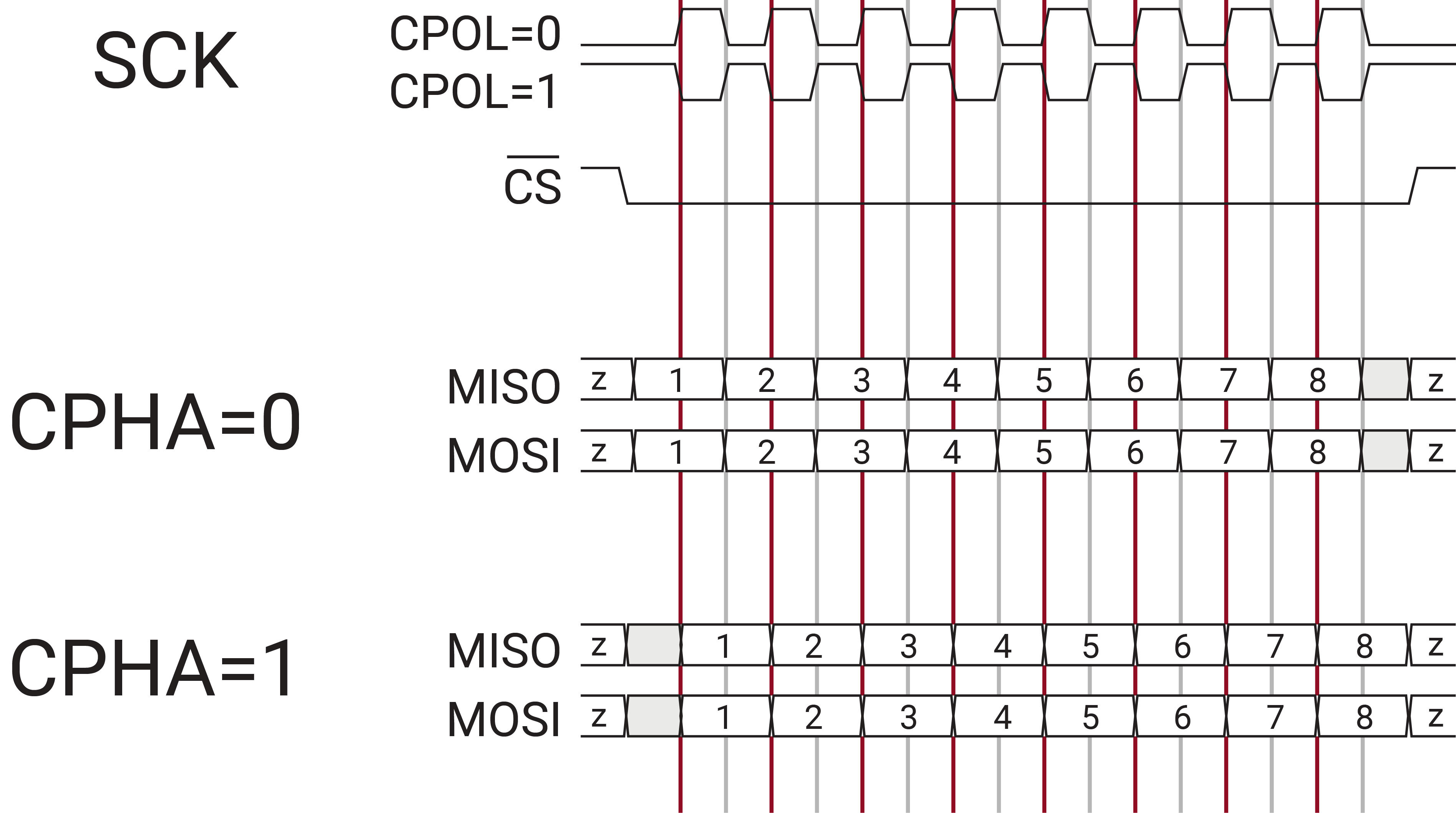
As displayed in Figure 4.4, the clock phase determines the timing in which the data is to be modified and read. If the clock phase is set to zero, the data is modified on the trailing edge of the clock signal and the data is read on the leading edge. Conversely, if this property is set to one, data is changed on the leading edge of the clock signal and read on the trailing edge. As the clock cycles, data is sent bit by bit, simultaneously, over the MOSI and MISO lines.
MOSI and MISO Signals
There are two data lines used in SPI communication known as MOSI and MISO. The MOSI signal sends data out from the master and is received by all slaves. Similarly, the MISO data line transmits data from one of the slave devices to the master device.
Chip Select Signal
The chip select pin is utilized by the master to select which slave to communicate with. This line for the specific slave should be pulled low when the master wants to communicate with the slave. If multiple slave devices are used on the same bus, then each slave will have its own dedicated chip select line, while sharing the clock and data lines. When the master is finished communicating with the slave, the chip select line is pulled back high.
