Educational Material
4.5 RF Hardware
The Global Navigation Satellite System (GNSS) relies on the use of radio-frequency (RF) waves to transmit the navigation message. Understanding how devices receive the waves is an important part of using the system. Once transmitted, a GNSS satellite's signal must be received by a device using an antenna. There are an assortment of antenna types available with different characteristics, cabling, and connectors as well as a variety of different antenna accessories.
GNSS Antennas
The three major antenna types used in GNSS systems are patch, helical, and choke-ring antennas. The shape of the sensing element that captures the RF waves is the major difference between them. Antenna design can also affect the gain, a measure of how well an antenna receives the intended RF energy. Receiving antennas are characterized by how efficiently they can capture the incoming signal from the direction of interest. This is known as the gain and is specified in units of decibels (dB). In general, larger antennas contain larger sensing elements which leads to higher gains.
Each antenna also has a location where the signal is tracked known as the phase center, which can vary over temperature and may be important in some applications.
Active vs. Passive Antennas
Passive antennas consist of only an RF receiving element and draw no power from the receiver while active antennas contain a low-noise amplifier and must receive power from the receiver through the RF connector. Active antennas typically add 3-50 mA of current draw to a system. The low-noise amplifier allows an active antenna to compensate for cable loss and increases the gain closer to unity.
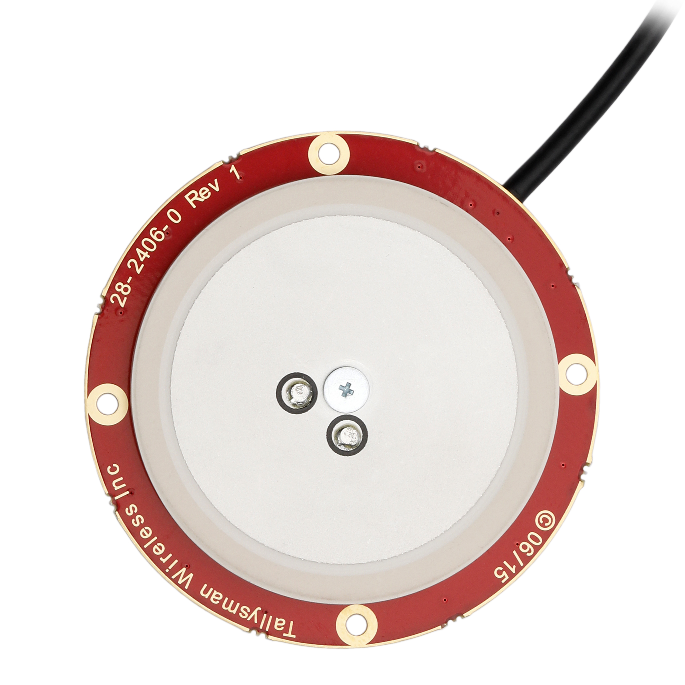
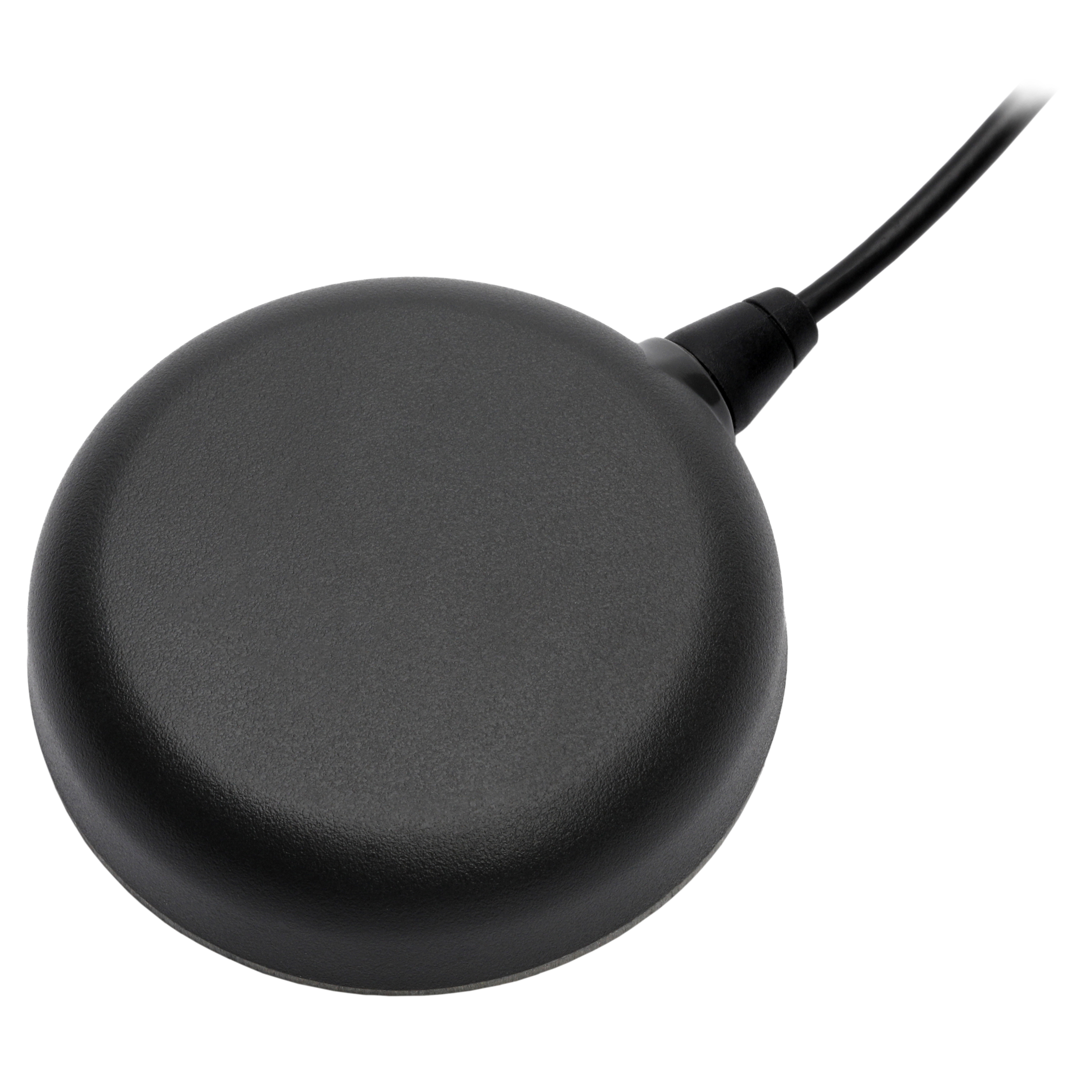
Patch Antennas
Patch antennas, also called microstrip antennas, consist of a sheet of metal that acts as the sensing element separated by an insulator from a larger sheet called a ground plane. This allows for a low-profile shape that is good for mounting on flat surfaces. The ground plane helps reduce multipath, but also makes patch antennas directional. Patch antennas can be cheaply and easily fabricated on printed circuit boards and are commonly used in mobile electronics. Patch antenna construction and an example product form can be seen in Figure 4.6.
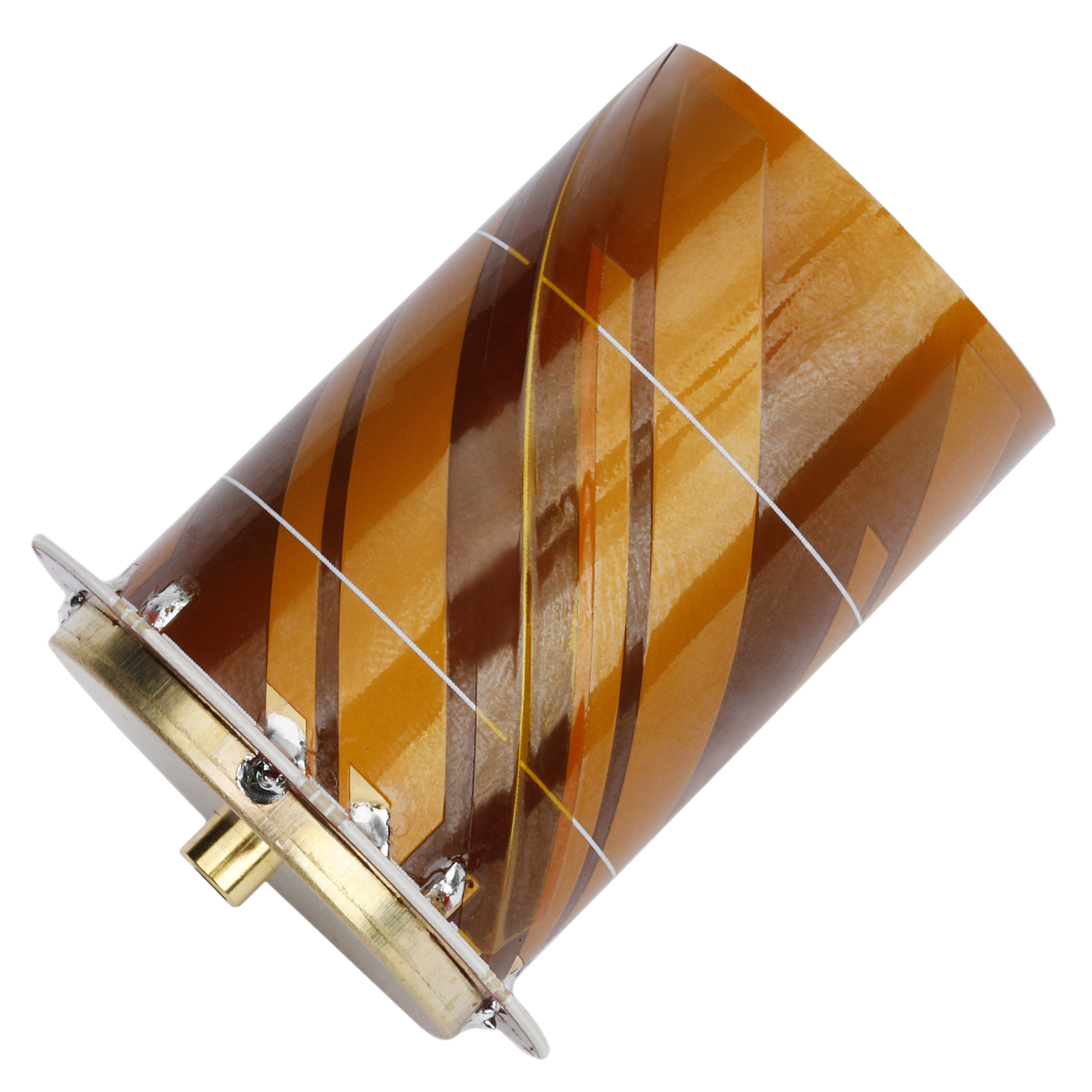
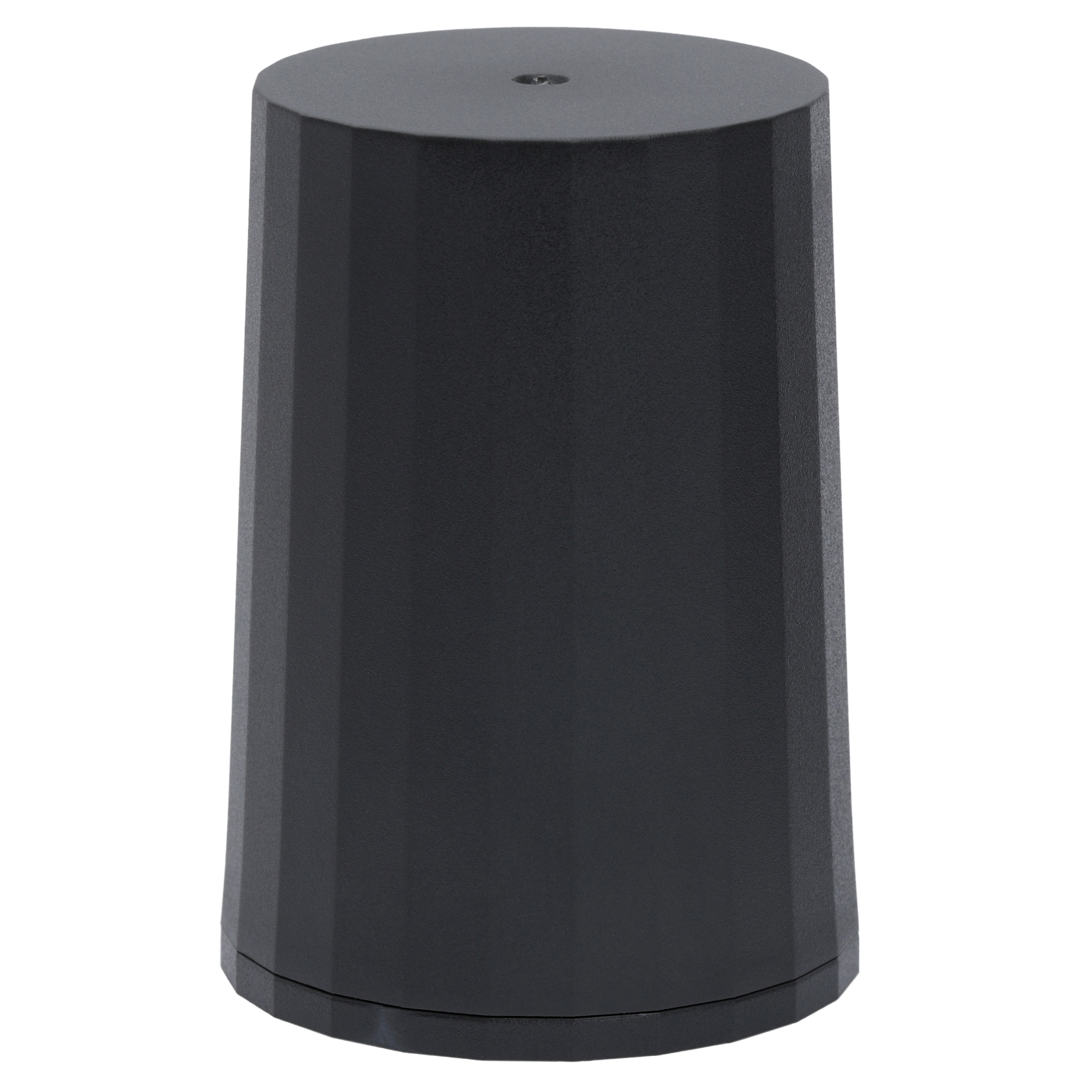
Helical Antennas
Helical or helix antennas are made of one or more wires wound into the form of a helix, and take a cylindrical shape, as seen in Figure 4.7. While most often mounted over a ground plane, omnidirectional designs can be achieved by omitting the ground plane. Helical antennas are versatile since they can operate in either normal mode or axial mode depending on the helix circumference relative to the intended wavelength. Normal mode is used when transmitting or receiving waves that are perpendicular to the helical axis, while the axial mode is for transmitting or receiving waves in the direction of the helical axis. These antennas can be made small enough for mobile applications or much larger. Due to their design, helical antennas are more susceptible to multipath.
Choke-Ring Antennas
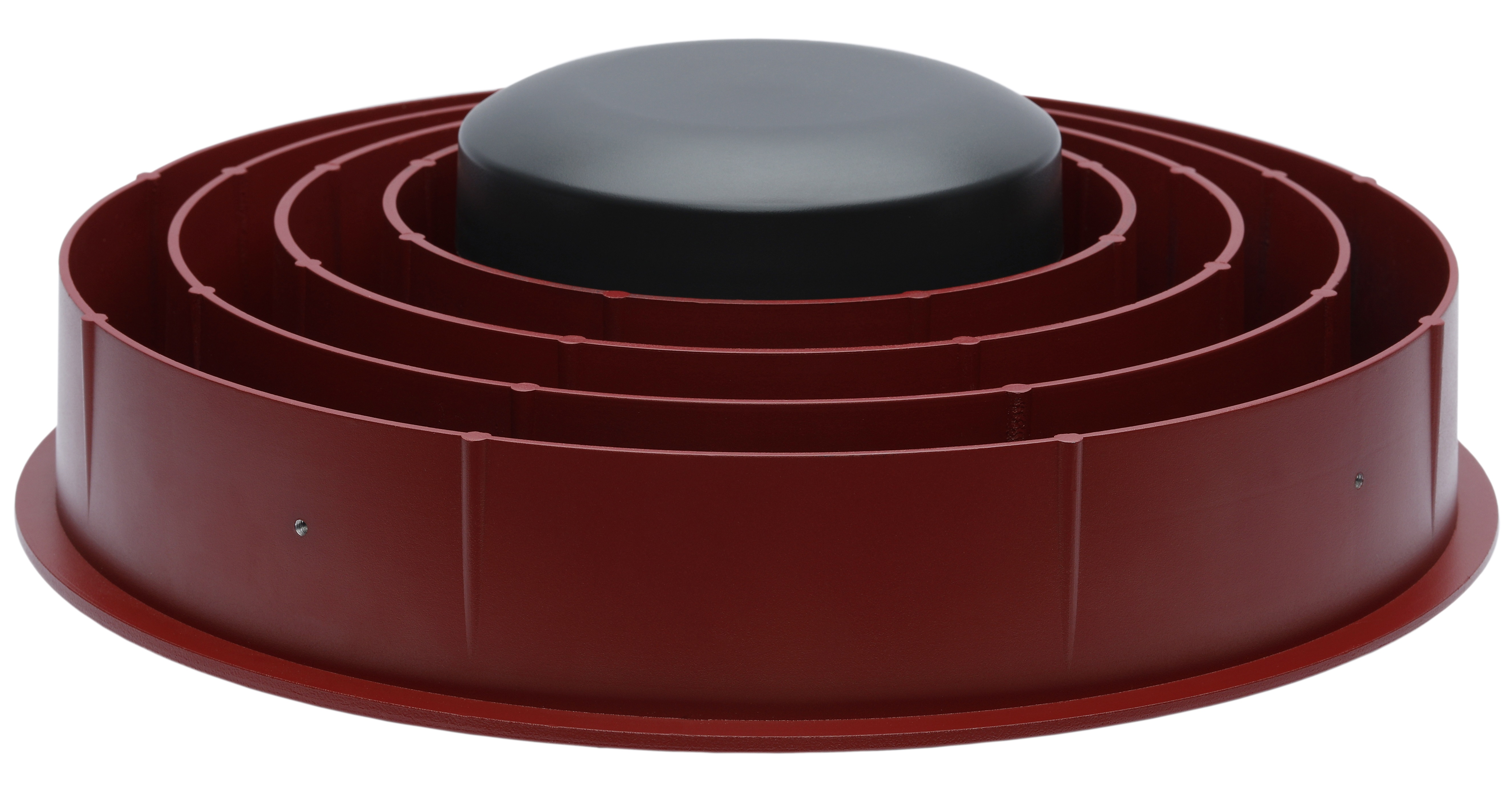
Choke-ring antennas are a directional design that consists of a central receiving element and a series of hollow concentric rings which act to greatly remove multipath signals. The multipath rejection and high phase-center stability of these antennas allow for the millimeter-level accuracy required for surveying applications. However, their large size makes them less ideal when mobility is required. A choke-ring antenna design is shown in Figure 4.8.
Ground Planes
The RF waves transmitted from the GNSS satellites can be susceptible to multipath interference, which occurs when the signals reflect off solid objects such as buildings and terrain prior to reaching the GNSS antenna. This causes the satellite signal to make multiple paths before reaching the GNSS antenna and can cause errors in the navigation solution. To prevent multipath interference from beneath the antenna, a ground plane is often mounted under the GNSS antenna. Ground planes can be any thin piece of metal, including foil, that block any multipath interference from reflecting up to the base of the antenna. Ground planes do not need to be electrically grounded.
RF Connections
GNSS signals occur below the noise floor and require special processing algorithms to recover the signal. For this reason, it is important to reduce any potential additional losses. Antenna characteristics, cable loss and connector loss can each contribute to how well a signal is received. The choice of cable, connector, and optionally a splitter, will have an effect on the GNSS signal strength.
Cables
Due to the high frequencies used in GNSS signal reception, coaxial cables are used. Coaxial cables consist of a central conductor surrounded by a dielectric, an outer conductor, and an outer insulator. Keeping cables short reduces GNSS signal strength loss, as does larger diameter cables.
Connectors
Figure 4.9 shows three common RF connectors: U.FL, SMA, and MMCX. Each varies in size and latching mechanism and force, so are useful for different applications.
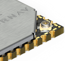
U.FL connectors are the smallest, commonly used to attach an antenna directly on an exposed PCB near a GNSS chip. These connectors are not meant to be attached or removed much as this can wear them out quickly. They can operate up to 6 GHz and are typically used for short distances. Shown in Figure 4.9a, a U.FL connector is typically only rated for ten connects and disconnects. Due to this, these connectors are designed for use as board to board connectors, rather than as panel mount connectors.
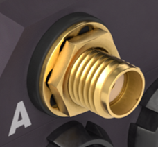
Sub-miniature version-A (SMA) connectors are available in male/female, but also in reverse polarity (typically denoted by RP) form that keeps the same electrical connections but puts the center pin on the threaded female connector. SMA connectors typically have performance up to 18 GHz and insertion loss as low as 0.17 dB. Figure 4.9b shows these connectors.
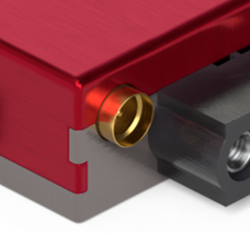
Micro-miniature coaxial connectors (MMCX) are smaller than SMA connectors and around a third of the weight. They have a 360-degree swivel mechanism and are popular in consumer electronics. MMCX connectors can operate up to 6 GHz with insertion loss of 0.3 dB and are designed for use as board to board connectors rather than as panel mount connectors. A MMCX connector is shown next to an SMA Connector in Figure 4.9c.
RF Splitters
RF splitters allow for multiple devices to receive the same GNSS signal. RF splitters divide a signal into 2 or more outputs, each having a fraction of the strength of the original. A 1-to-2 splitter will have a 3 dB decrease (50% power) on each output. Larger splitters are usually made from combinations of 1-to-2 splitters, so each additional division will lower the strength by 3 dB. It is important not to split a signal too many times or it may become difficult to recover for the GNSS receiver without adding another amplifier (which increases noise). In addition, splitters often contain DC blocks on all but one antenna to prevent multiple powered antenna sources from being in parallel and damaging each other. The low-noise amplifier on an active antenna only needs one source of power.
