Educational Material
4.1 Asynchronous Serial Communication
Asynchronous serial communication is a communication interface in which the signals used are not synchronized to each other using a common clock signal. Instead, start and stop bits are used to indicate the beginning and end of a data message. This type of communication utilizes a point-to-point type of interface, meaning that only two devices can be linked together to communicate. These two devices must also agree upon the rate at which bits will be transmitted and received, known as the baud rate, since there is no clock signal to indicate such transitions. Furthermore, asynchronous serial communication can be implemented in either a full-duplex (independent transmit and receive lines) or half-duplex (shared transmit/receive line) configuration, making it a versatile communication protocol that can be used in many different applications.
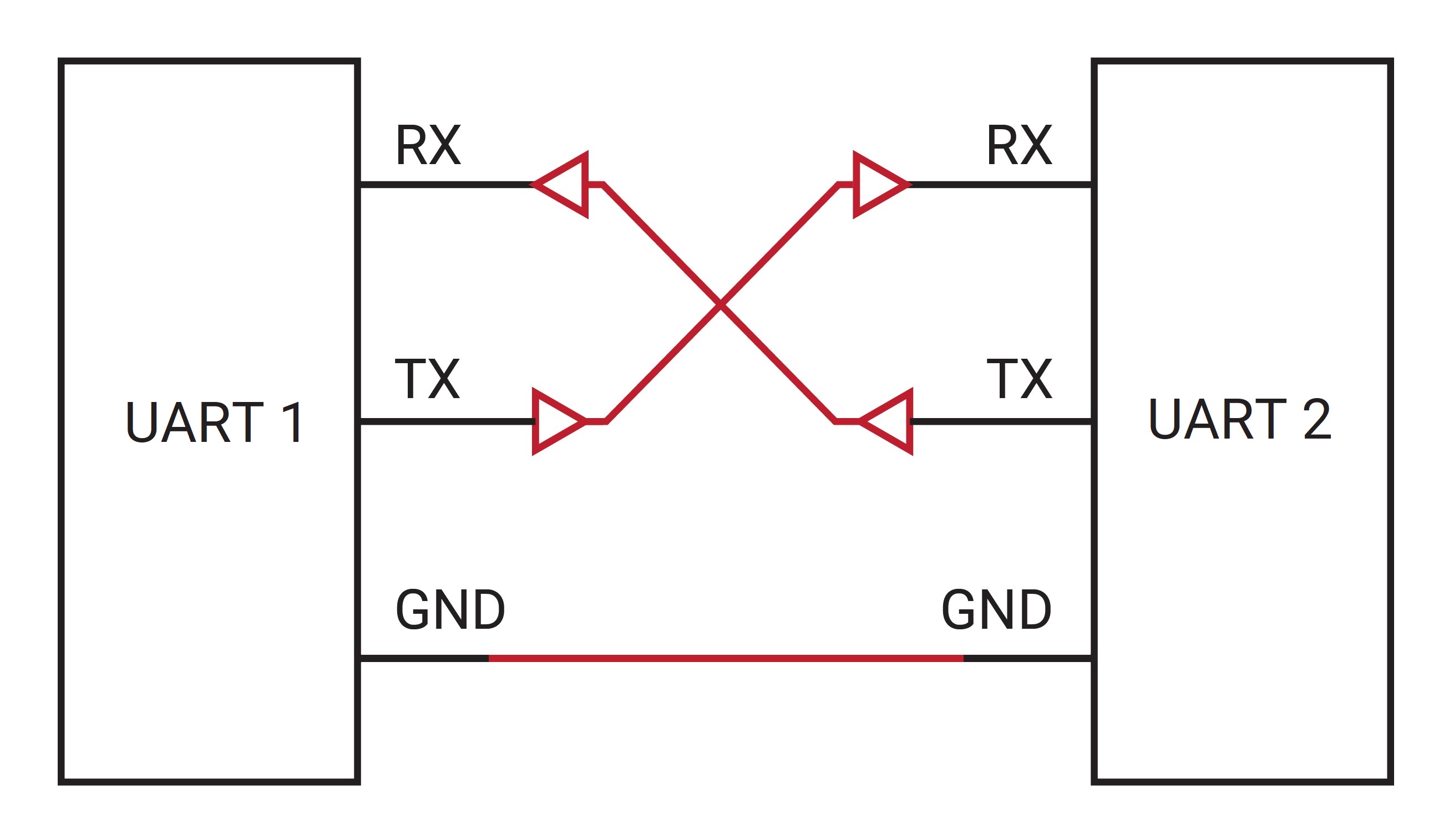
The asynchronous serial communication interface utilizes a receiving signal (RX) and a transmitting signal (TX). When connecting two devices to communicate in full-duplex mode, the RX pin of one device must connect to the TX pin of the other device, as shown in Figure 4.1. Asynchronous serial communication is most commonly implemented using a universal asynchronous receiver-transmitter (UART). UARTs are typically employed in microcontrollers, but can also exist as individual integrated circuits (ICs).
Asynchronous serial communication using a UART interface is very commonly used due to the minimal amount of wires needed for communication and very simplistic protocol required for sending messages. It allows the ability to modify the data packet based on the needs of the application and does not require a separate clock signal to transmit data. However, a UART interface can only be used to communicate between two devices and requires that the baud rates and the bit packets on both devices be the same, or data will be misinterpreted.
Configuration
Data transmitted using asynchronous serial communication or via a UART is sent as packets of bits. These packets contain a start bit, a configurable number of data bits (5-9), an optional parity bit, and a configurable number of stop bits (1-2). The most common structure of a UART bit packet is known as 8-N-1, corresponding to eight data bits, no parity bit, and one stop bit. These bits combined with one start bit create a bit packet that is a total of ten bits long. Both devices communicating via the serial bus must be configured for the same bit packets and transmitting those bits at the same speed, known as the baud rate. The serial port configuration is often prepended with the baud rate: 115200-8-N-1.
Start & Stop Bits
The start and stop bits are known as synchronization bits as they indicate to the receiving device when the packet begins and ends. Asynchronous serial communication data lines are held in a high idle state when not transmitting data. The start bit transitions the data line from a high (1) to a low (0) state. Once the receiving device identifies this transition as the start bit, the 5-9 data bits are read at the specified baud rate. The stop bit indicates the end of the data packet by pulling the data line back to the high (1) idle state.
Parity Bit
The parity bit is an optional bit that provides a very low-level form of error detection as data bits can be altered from things like electromagnetic interference or lengthy data lines. If used, this bit can either be specified as an odd parity or an even parity. An odd parity determines whether the data bits in the bit packet contain an odd number of 1-bits. If there are an odd number of 1-bits, the parity bit is set to 0, if not the parity bit is set to 1. This ensures that the data bits combined with the parity bit contain an odd number of 1-bits. Similarly, an even parity will set the parity bit to 0 if the number of 1-bits in the data message is even, otherwise, the parity bit will be set to 1. If one of the data bits have flipped value during transmission, the parity bit will indicate that the number of 1-bits is incorrect. However, the parity bit is not often used as it is unlikely to detect that the message is incorrect if more than one-bit has flipped.
Baud Rate
An important parameter when using asynchronous serial communication or when interfacing with a UART is how fast data can be transmitted across a serial line. The number of bits per second sent over a UART is defined as the baud rate. Possible baud rates span a wide range and can be almost any value, but since both devices must support the same baud rate, certain values have become standard baud rates. As the baud rate increases, the amount of time required to send or receive data decreases. Table 4.1 provides a list of standard baud rates and the amount of time required to transmit 100 bytes of data using the standard 8-N-1 configuration (requiring 10-bits per byte of data).
| BAUD RATE | TIME FOR 100 BYTES |
|---|---|
| 9600 | 104.2 ms |
| 19200 | 52.1 ms |
| 38400 | 26.0 ms |
| 57600 | 17.4 ms |
| 115200 | 8.7 ms |
| 230400 | 4.3 ms |
| 460800 | 2.2 ms |
| 921600 | 1.1 ms |
Hardware Implementations
Asynchronous serial communication can be implemented in many different ways, depending upon the application it is being used in. Some of the more common standards include transistor-transistor logic (TTL), RS-232, and RS-422 or RS-485. Each of these implementations determine whether a signal is low (0-bit) or high (1-bit) based on different thresholds for the amount of voltage transmitted across a line. Due to the different voltage levels used, connecting two devices with different hardware standards can cause damage to one or both devices.
Transistor-Transistor Logic (TTL) Level
Transistor-transistor logic (TTL) is a physical implementation of asynchronous serial communication, ideal for board-level communication as the wiring must be less than a few feet long. This type of hardware implementation uses a single-ended type of signal, meaning that the voltages sent across the communication lines are referenced to the ground signal. TTL is most often utilized when communicating through a UART interface in microcontrollers or integrated circuits.
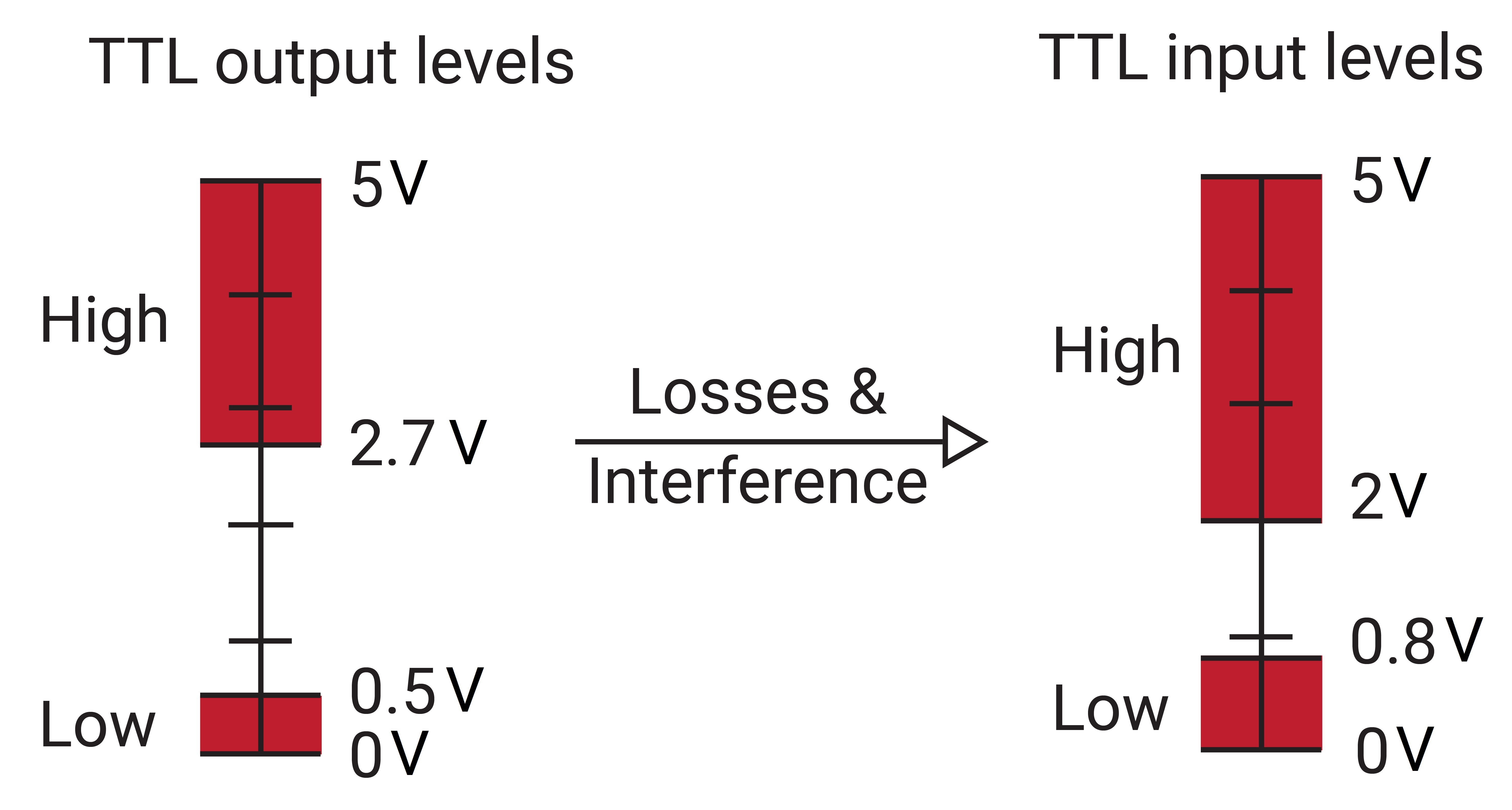
As shown in Figure 4.2, the low state (0-bit) is considered any voltage between 0 V and 0.8 V, while the high state (1-bit) is regarded as any voltage between 2 V and 5 V. The difference in acceptable voltage levels for input and output allows for loss and noise on the signal line. TTL idles in the high state.
RS-232
The most common type of hardware implementation for asynchronous serial communication is known as RS-232. This type of interface often uses cables to connect devices and commonly supports cable lengths of up to 10 m, allowing its use in many applications. Similar to TTL, RS-232 also utilizes single-ended signals and idles in the high-state, but uses voltages ranging from -15 V to 15 V. The voltage threshold for the low-state (0-bit) ranges from 3 V to 15 V, while the threshold for the high-state (1-bit) ranges from -15 V to -3 V.
RS-422/RS-485
The RS-422 hardware implementation of asynchronous serial communication is a standard frequently used in industry. Differing from TTL and RS-232, RS-422 uses differential signals which measures the voltage difference between two wires rather than comparing a signal to a common ground. Using differential signals provides greater robustness to interference and cable losses, allowing RS-422 to operate over much greater distances than RS-232 or TTL.
Typically, the differential signals are referred to as $RX^+$ and $RX^-$ lines for receive, and $TX^+$ and $TX^-$ lines for transmit. However, these lines are sometimes referred to instead as $RX^A$, $RX^B$ and $TX^A$, $TX^B$ or as the inverted signal and the non-inverted signal. Unfortunately, the RS-422 standard does not specify the nomenclature of the particular signals, only the signal levels. This means that each manufacturer of a device can choose their own signal names and pinouts. Due to this, care must be taken when connecting two devices to ensure that the signals are matched correctly.
RS-422/RS-485 systems can be configured using either a full-duplex or half-duplex arrangement. A full-duplex configuration contains both RX and TX communication signals allowing the two devices to transmit data to each other independently and simultaneously. The half-duplex configuration utilizes a single shared communication signal, meaning that only one device can transmit data at a time, and half the wires are needed. Half-duplex configurations are advantageous when there are constraints on the number of wires to be used or if the communication is only in one direction.
