Educational Material
4.4 Electrical Interfaces
Outside of the data transmission pins described in the communication sections, there are a number of other electrical interfaces for powering and synchronizing to inertial systems that require care. Unregulated voltage, floating signal pins, and electrostatic discharge can have unintended effects on an electronic system. Voltage regulators, pull up/down resistors, and standard grounding practices are used to prevent these issues.
Voltage Regulation
A voltage regulator is a device that is designed to automatically regulate a voltage level when a stable and constant voltage is required. Voltage regulators are able to maintain a steady output voltage for significant changes in input voltage or load conditions. There are two types of voltage regulators: linear voltage regulators and switching voltage regulators.
Linear Regulator
Linear voltage regulators operate like a variable resistor, using closed feedback loops to maintain a constant output voltage as the input voltage or current load varies. All linear regulators require a higher input than the output meaning that the output voltage will always be less than the input voltage. Voltage regulation is accomplished by dissipating the excess voltage as heat. Like a variable resistor, the current draw at the input and the output are identical. A linear regulator's efficiency is equal to the ratio of the output voltage to the input voltage.
The minimum voltage difference between the input and the output voltage needed to supply a desired current is called the dropout voltage. Having a larger voltage difference between the input and the output or having a larger current means that there will be more power loss in the form of dissipated heat. For cases where the input voltage is very close in value to the output voltage, low-dropout (LDO) regulators are required.
Linear regulators are designed to have the advantage of having a very low ripple output voltage with very little noise coupled into the DC output. This makes them useful for sensitive analog electronics, like many inertial sensors or RF systems, but their low efficiency for large voltage drops limits their utility.
Switching Regulator
Switching regulators are a type of voltage regulator that rapidly switch a series device on and off, such that the average voltage at the output is correct. Capacitors and inductors are used to smooth this on-off voltage into a smooth, steady output voltage, though with considerably higher output voltage ripple than a linear regulator.
Unlike linear regulators, a switching regulator is able to produce output voltages that are higher than the input voltage or of opposite polarity. There are two main types of switching regulators: step-up, or boost regulators, and step-down, or buck converters. Step-up regulators provide a higher output voltage by increasing or stepping-up the input voltage. Conversely, step-down regulators perform the opposite action of the step-up regulator by lowering the input voltage to a desired regulated output.
Most switching regulators operate at 100s of kilohertz which is a common source of EMI in inertial systems. Furthermore, the requirements for capacitors and inductors to smooth and stabilize the output generally requires more components and board space than a linear regulator. However, switching regulators often operate at efficiencies of 80-90%, making them ideal for large voltage drops.
General Purpose Input/Output (GPIO)
A general purpose input/output is an uncommitted digital signal pin on an integrated circuit whose behavior (being in an input or output state) is controlled by the user. Hence, they can be configured as either an input or an output pin.
Input & Output Modes
When a GPIO is configured as an input pin, there are three configuration modes that can be assigned to the pin: high-impedance, pull-up, or pull-down. As stated in the tri-state logic section, high-impedance is the default state and is a floating pin. The pull-up mode uses an internal resistor to connect the input pin to Vcc. The pull-down mode uses an internal resistor to connect the input pin to ground.
When a GPIO in configured as an output pin, there are two configuration modes that can be assigned to the pin: push-pull and open-drain. The push-pull pin mode connects the output pin to either Vcc or ground and thus has the ability to source or sink the current. The open-drain mode has two the ability to achieve two output states: low-impedance and high-impedance, referring to the amount of resistance to current flow. Unlike the push-pull mode, open-drain only has the ability to sink current. In order to achieve a high state, an additional pull-up resistor is required to connect to the desired voltage level.
Tri-State Logic
In digital electronics, tri-state or three-state logic states that a pin can assume three independent states: logical 0, logical 1, and high-impedance. Logical 0 means that the connection is to the ground reference, logical 1 means that the connection is to Vcc and lastly the high-impedance state, also known as Hi-Z, effectively removes the devices influence from the rest of the circuit. Alternatively, the term "floating" can be used for a pin which is in Hi-Z mode due to the fact that the pin is connected to neither Vcc nor ground.
Pull-Up & Pull-Down Resistors
A schematic showing the implementation of pull-up and pull-down resistors is shown in Figure 4.5. A pull-up resistor holds an input pin in a high state unless the input is shorted to ground, whereas a pull-down resistor keeps an input pin in a low state unless it is shorted to Vcc. This is useful to guarantee that in an input pin is in a known state when nothing is otherwise connected to it without impeding normal operation. Connecting the pins directly to Vcc or ground would render the pin inoperable because a device connected to that pin would create a short circuit when attempting to signal low or high, respectively.
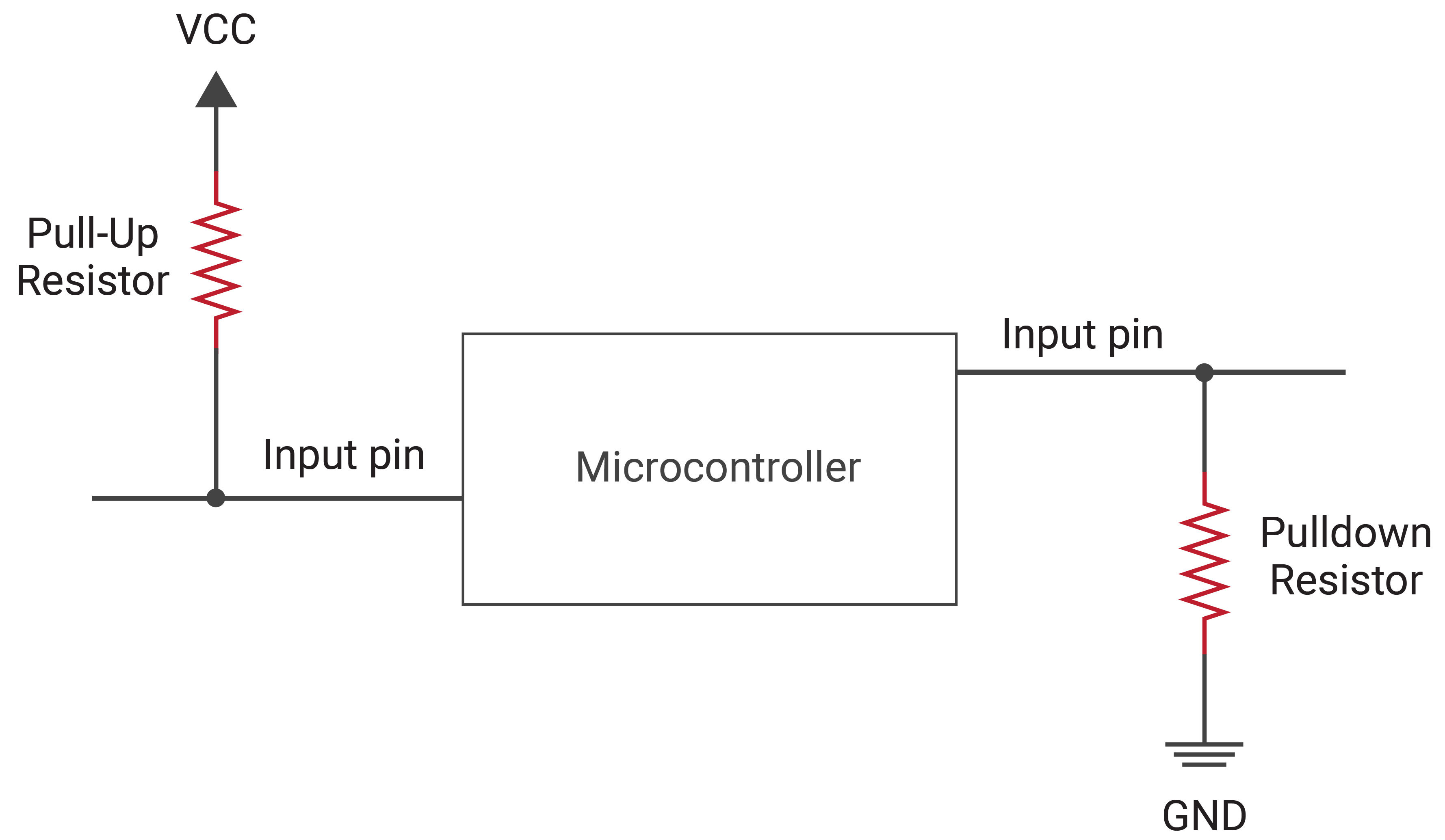
A typical pull-up/down resistor value ranges from 1-10 kΩ, but can go as high as 100 kΩ depending on the application. A lower valued resistor is considered a "stronger" pull-up/down, while the higher valued resistors are considered "weaker", based on the current draw that is required to toggle the state of the pin. A stronger pull-up/down requires a greater current draw, and therefor reduces the likelihood that transients on a signal line (noise, EMI, etc) will cause a false trigger on the input pin.
It is important to note that a weaker pull-up/pull-down will result in a slower voltage change on an input pin due to the coupling of the resistor and the wire capacitance which forms an RC circuit. The larger the product between these two values, the more time is required for the capacitance to charge and discharge due to the resultant time constant value.
IO Speed (Slew Rate)
GPIO speed is what controls the rate at which a signal can change between high and low states. Common terms for IO speed include "frequency" and "slew rate" as they are generally used synonymously. The speed of the signal is dependent on signal path capacitance as the capacitance will slow voltage rise/fall times of the signal. Higher IO speeds increase the rate of change of the output voltage meaning that the rise time of the signal is reduced. However, this requires high power consumption and causes an increase in radiated noise such as Electromagnetic Interference (EMI).
Electrostatic Discharge (ESD)
Electrostatic discharge is the sudden flow of electricity between two objects that have different charges and number of electrons. The flow of electricity from one object to another creates a dielectric breakdown, sometimes creating a visible spark. ESD is an important phenomenon to be aware of due to its ability to cause damage to electrical components and potentially start fires or create explosions. Damage caused by ESD can be difficult to detect and may result in reduced system life, leading to an early failure long after the actual ESD event.
Therefore, it is important to protect sensitive components, especially microchips, during the manufacturing, assembly, and shipping processes from potential ESD occurrences. Additionally, users must be mindful when working with a device or component by hand as they may have accumulated an electric charge that can be dissipated via ESD through to the device. Due to this, it is important to follow proper safety and grounding procedure to combat any possible instances of ESD, such as wearing grounded wrist-straps at workbenches.
