Educational Material
4.6 Electromagnetic Interference (EMI)
When designing or integrating a product it is important to take electromagnetic interference (EMI) into consideration. Failing to account for the various types of EMI for both emissions and sensitivity can result in unexpected system behavior or even failure.
Transmission Modes
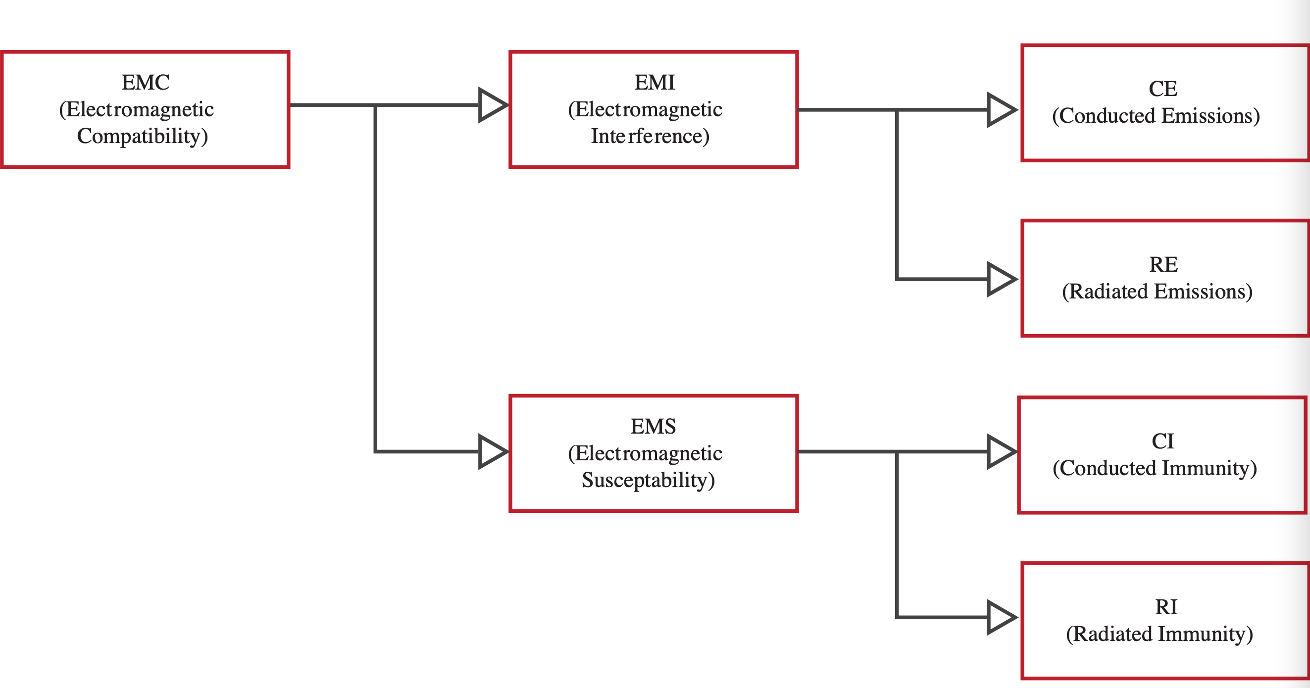
The two main modes of action for EMI are through conducted and radiated means. Conducted types involve noise that passes through a conductor into or out of a device, while radiated noise is received or transmitted wirelessly. It is also possible for a combination of noise types to be present within a system, and that multiple mitigation methods will be required. The various types can be seen in Figure 4.10, and testing for each of them is described in detail by MIL-STD-461, which is described in more detail in Section 6.4.
At lower frequencies, noise usually travels through conducted means, while at higher frequencies, it is more often radiated. It is also often the case that a device will be vulnerable to the same frequencies that it is emitting. It is also possible that what appears to be conducted noise may be the result of a radiation issue, such as cable cross-talk in cable bundles or PCB layout issues.
Conducted Susceptibility/Immunity (CS)
Conducted susceptibility is the vulnerability of a system to noise that enters through a conductive path, such as power inputs/returns. A device may share a power rail with multiple other devices and each one could contribute noise to the rail, so it is important to ensure that all devices can continue to function properly. At the printed circuit board level, most integrated circuits recommend decoupling capacitors located near the power pins to prevent high frequency noise from entering the IC. This can be applied to the overall system as well with some success, depending on the frequencies of noise involved. It may also be beneficial to include a low-pass filter designed to attenuate the frequency of noise present.
Conducted Emissions (CE)
Conducted Emissions is the noise that a system puts out onto its conductive connections that could interfere with another device. Locating and altering the noise source to no longer output noise that reaches the power rails is the ideal option. Where this is not possible, adding filtering can usually reduce this noise. This type of noise is commonly associated with switching power supplies/regulators. Cable cross-talk could also give the appearance of conducted noise. The use of individual twisted, shielded pairs in a cable can help reduce the effects.
Radiated Susceptibility/Immunity (RS)
Radiated Susceptibility is the vulnerability of a system to wireless noise from the surrounding environment. A device must be able to encounter a reasonable level of outside interference and still function properly. Proper shielding such as a Faraday cage equivalent chassis can help block out radiated noise, as well as twisted shielded pairs in cables. Filters and internal shielding around sensitive components may be necessary if it is not possible to prevent radiated noise from entering a device.
Radiated Emissions (RE)
Radiated Emissions is the noise a system puts out into its environment. It is important that this noise be at an acceptable level to not cause any issues withing surrounding systems or equipment. Design factors such as case material and cable selection can play a huge role in radiated emissions. A well shielded setup will radiate very little noise. If shielding the entire setup is not an option, it may be helpful to locate the radiating source within the device and find a way to attenuate it there, such as localized shielding or using a different part operating at a different frequency.
Mitigation Techniques
While mitigating the effects of EMI, whether emitted or received can influence design choices throughout the entire system, careful use of grounding, shielding, and filtering of problematic lines can significantly reduce EMI effects with minimal impact.
Shielding
The best way to shield a device is to emulate a Faraday cage. A Faraday cage surrounds an object with a conductor which helps block or greatly reduce most electromagnetic signals from reaching the inside. While a solid conductor works best, a mesh can be applied as long as the holes in the mesh are smaller than the wavelength of the signals being blocked. By selecting a metal chassis as a device enclosure, a Faraday cage-like effect is achieved.
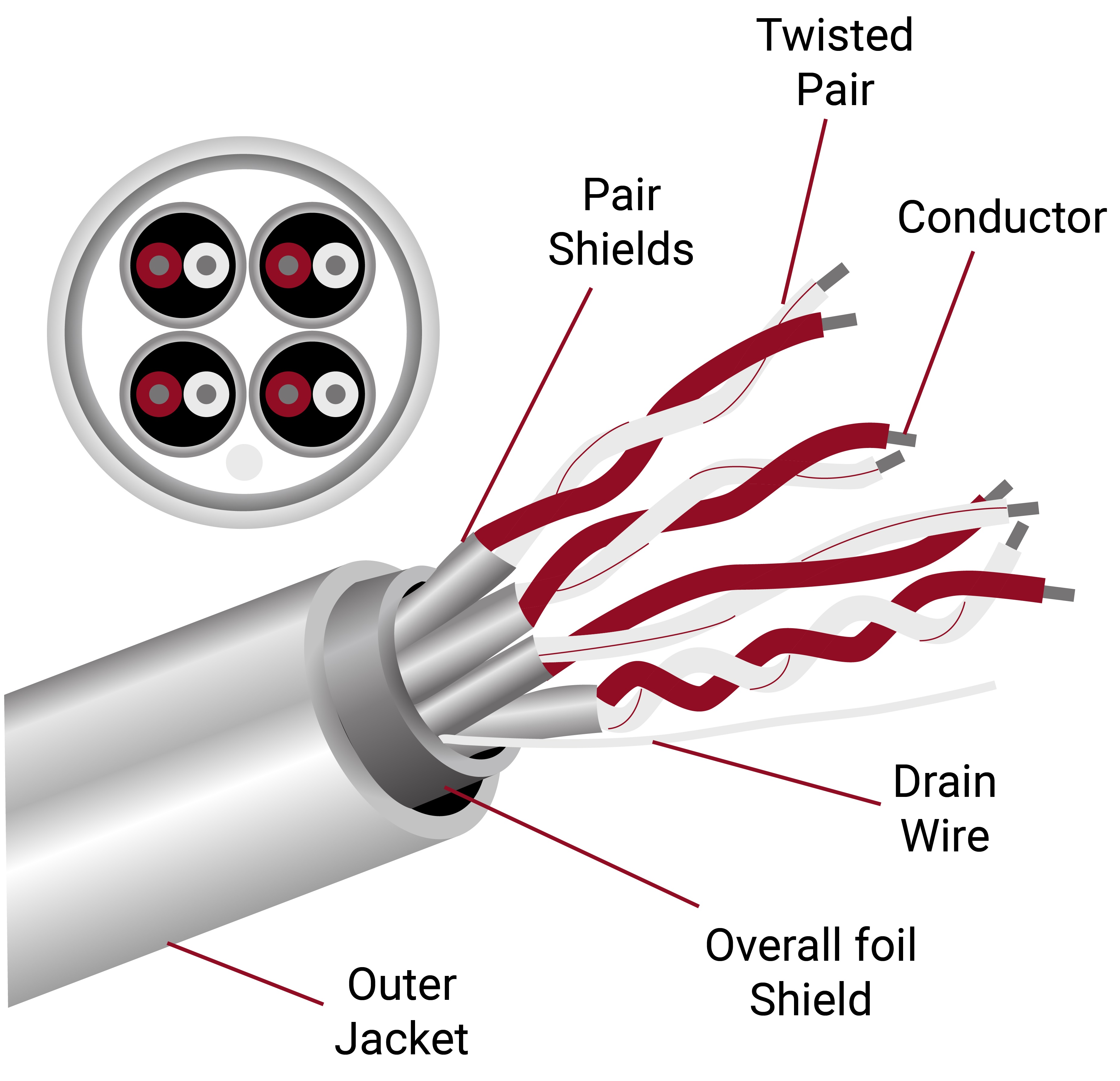
Cables and connectors will require openings in the cage that noise could still get through. Using metal connectors can help when paired with cable shielding. There are a few different types of cable shield and ways to attach that shield to the connector on each end. While an overall cable shield helps with emissions, individual pair shields as shown in Figure 4.11a can help in keeping noise from coupling into adjacent wires or becoming 'conducted emissions' on power leads. Foil shield does a better job than braided shield at high frequency, but is not as mechanically strong. Some cables use a combination of braided and foil shielding to get the advantages of both. Using twisted pairs also helps to reduce common-mode noise, which is noise that occurs on both conductors.
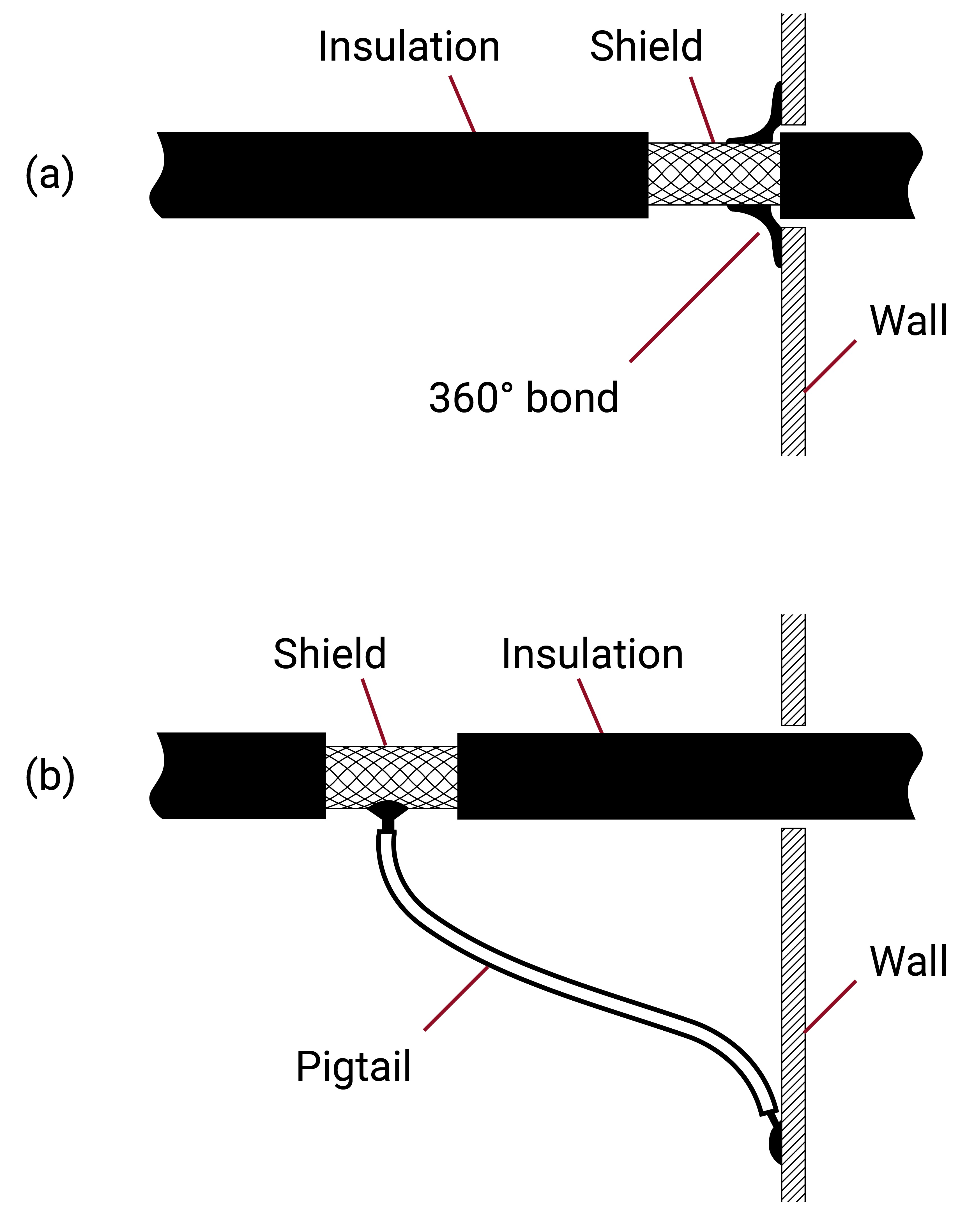
Cables also need their shield tied to ground at both ends, where possible, to help with the Faraday effect. The way that this is done can also have an effect on EMI. Creating a 360° bond is more effective than just connecting the shield to the chassis with a wire 'pigtail', as shown in Figure 4.11b.
Filtering
When shielding techniques are not enough, adding a filter can assist in conducted EMI reduction. A low-pass filter consisting of an inductor and capacitor can attenuate high frequencies while leaving DC voltages alone. A band-stop filter may be a better tool in some cases, as it can attenuate noise in a range while leaving the remaining frequencies unchanged. Many different filter configurations exist, with most having online calculators to help in designing to filter a certain problem frequency.
