Educational Material
5.2 Enhanced GNSS Technologies
Increasingly, systems must navigate in GNSS-challenged environments in which GNSS may be susceptible to jamming, spoofing, or unintentional interference. The use of enhanced GNSS technologies, including specialized hardware, sophisticated algorithms, and additional GNSS signals, can provide robustness during operation in GNSS-degraded conditions.
Military GPS Receivers
As discussed in Section 1.5, a GPS satellite signal has three components: the carrier, the code, and the navigation message. The code portion of the signal allows all satellites on the band to transmit on the same frequency without interfering with one another. While standard GPS positioning utilizes publicly available code signals, these signals can be spoofed with false information, leaving users vulnerable to such attacks. To combat spoofing, the U.S. military developed encrypted code signals that are broadcast by the GPS satellites. These signals can only be decrypted by specialized GPS receivers: SAASM receivers and M-code receivers.
SAASM Receivers
At the creation of GPS, two different positioning services were offered: the Standard Positioning Service for public use and the Precise Positioning Service for authorized military users. During the 1990s, the publicly available service was intentionally degraded to limit the position accuracy that civil users could obtain through a feature known as Selective Availability (SA). The Precise Positioning Service utilized Precise code (P-code) which was encrypted with W-code to become P(Y)-code to protect authorized users from false GPS signals generated during a spoofing attack.
While Selective Availability was deactivated in the early 2000s, the P(Y)-code remains encrypted to provide anti-spoofing (AS) capabilities. To decrypt the P(Y)-code, authorized users must utilize a specialized receiver called a Selective Availability Anti-Spoofing Module (SAASM). SAASM receivers are commonly employed in military applications and are often a requirement for military systems needing GPS. While a SAASM receiver provides robustness to spoofing, the P(Y)-code signals are still relatively weak when received on Earth, leaving SAASM receivers vulnerable to jamming.
M-Code Receivers
To enhance the security of GPS systems for the U.S. military and its allies, an encrypted signal called M-code was developed. Representing the latest development of the GPS constellation, the M-code signal is an encrypted signal added onto the L1 and L2 GPS bands that allows for the GPS signal to be transmitted at a higher power without interference to the civilian C/A code or previous military P(Y)-code. Since M-code is an encrypted signal, authorized users must utilize a specialized receiver called an M-code receiver to decrypt the signal.
Similar to a SAASM receiver, an M-code receiver can reject false signals and provide robustness to spoofing. However, compared to a SAASM receiver, an M-code receiver provides the advantage of being more resistant to jamming due to the higher transmission power of the M-code signal. M-code is expected to replace P(Y)-code, with many military applications already upgrading from legacy SAASM receivers to M-code receivers to take advantage of the anti-jamming and anti-spoofing capabilities.
Anti-Jam Antennas
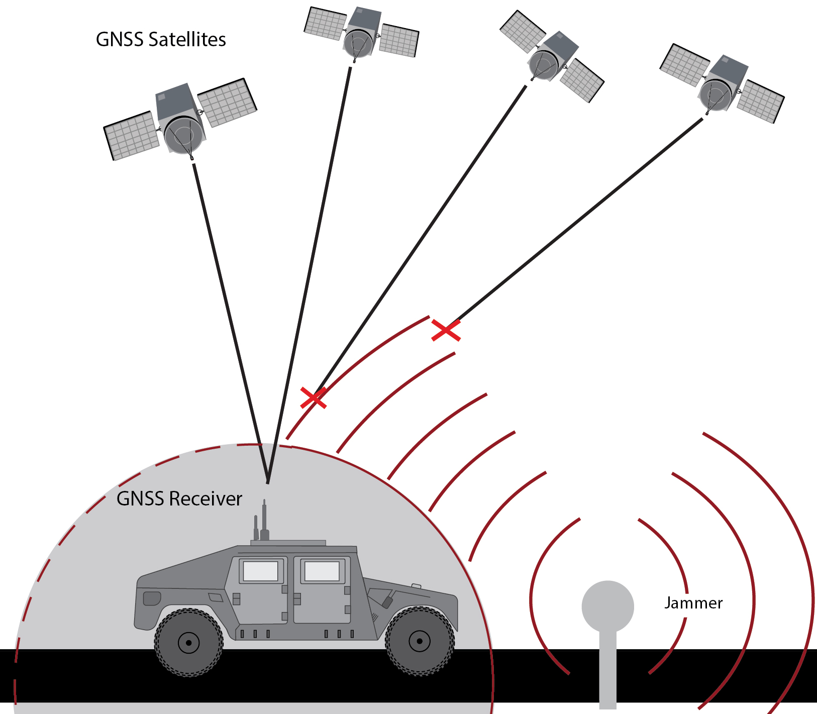
GNSS jammers drown out the relatively weak GNSS signals by generating a far stronger signal in the GNSS frequency band(s), preventing a GNSS receiver from tracking the real signal (see Section 5.1). A specialized antenna—the Controlled Reception Pattern Antenna (CRPA) (also referred to as an anti-jam antenna)—is often utilized to combat GNSS jamming as seen in Figure 5.3. The main advantage of a CRPA is that it can provide resistance to jamming by simply swapping out the GNSS antenna without impacting other components in the navigation system.
A CRPA consists of multiple antenna elements that are spatially distributed, making the CRPA larger than typical single-element patch antennas. Signals from different directions strike these different antenna elements at different times. Electronics inside the CRPA can amplify or attenuate different signals by varying the phase shift applied to each element when combining them into a single RF output used by the GNSS receiver. Amplifying a particular signal is often referred to as beamforming or beam-steering while attenuating a particular signal is referred to as nulling or null-steering.
While the algorithms behind beamforming (amplifying the GNSS satellite signals) and nulling (canceling the jamming signal(s)) are complex and proprietary to each manufacturer, they typically take advantage of two methods for distinguishing the jamming signal(s) from the satellite signals. The first is spatial distribution: GNSS satellites are typically above while jammers are typically at the horizon or below. The second is a difference in power: jammers generate a signal many times stronger than the satellites. Because of these two distinctions, CRPA antennas can perform beamforming and nulling without feedback from the GNSS receiver.
A CRPA is capable of nulling up to $n-1$ jammers, where $n$ is the number of antenna elements, but it is most effective when there are significantly more elements than jammers. Those extra antenna elements allow the optimization algorithms more degrees of freedom to effectively null the jammer(s) while maximizing the satellite signals. The effectiveness of this nulling, measured by the attenuation in decibels (dB), also varies between manufacturers due to the algorithms they employ.
Tightly-Coupled GNSS/INS
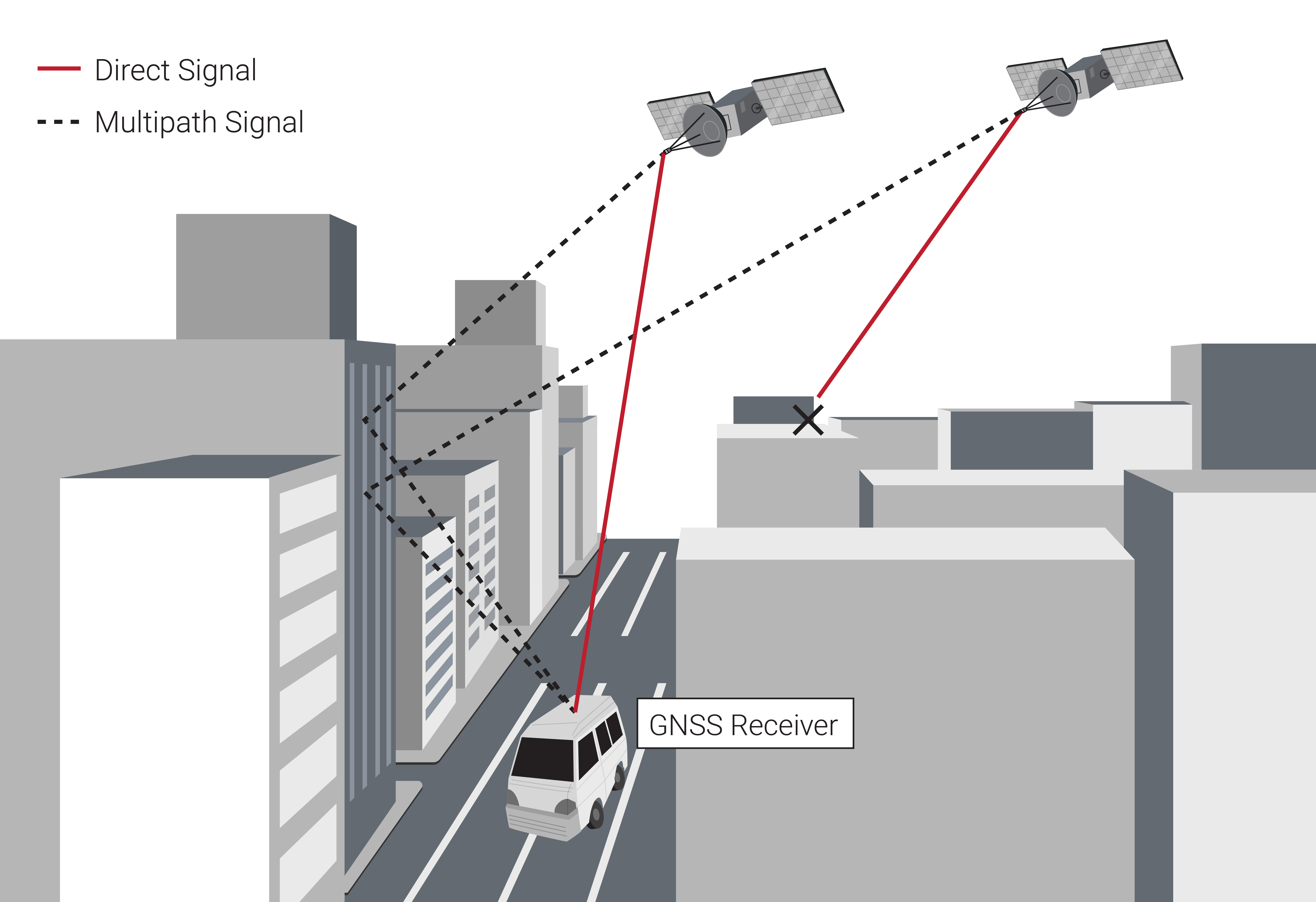
Most commonly, a GNSS receiver is combined with an INS system using a loosely-coupled approach, which incorporates a GNSS receiver's calculated position, velocity, and time (PVT) with the inertial sensor measurements to provide a fused position, velocity, time, and attitude solution. However, this approach necessitates that four direct line-of-sight satellites are in view of the GNSS antenna. Some environments are prone to structures that block and reflect a GNSS signal—the classical example of this is an urban canyon as shown in Figure 5.4.
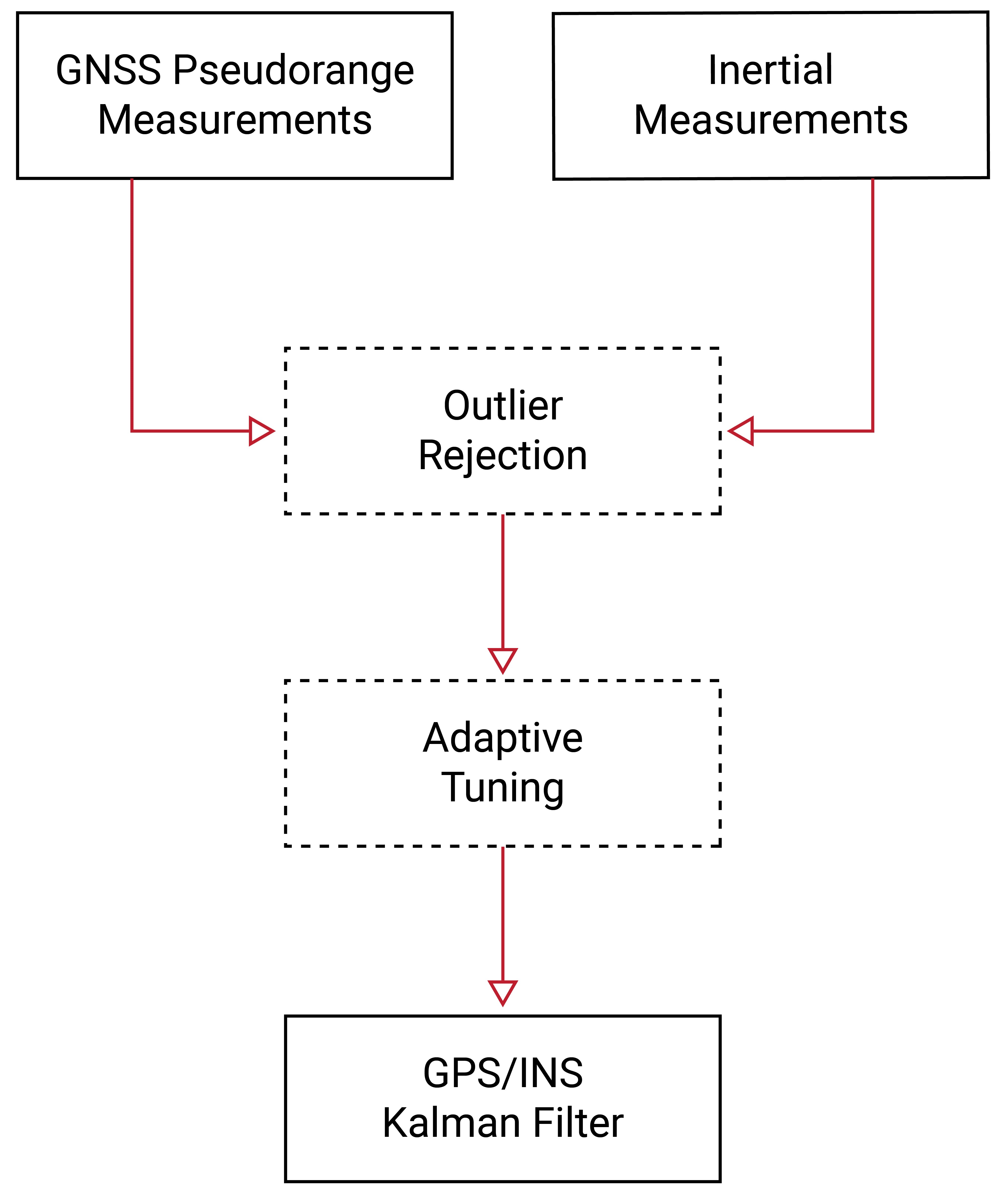
In restricted visibility environments, it may not be possible to acquire a signal lock on four direct line-of-sight satellites. Rather than using the GNSS receiver's calculated navigation solution, a tightly-coupled GNSS/INS filter combines the raw GNSS pseudorange and Doppler measurements directly with the inertial sensor measurements in an extended Kalman filter, as displayed in Figure 5.5. Such an approach still estimates the fused position, velocity, time, and attitude of the system; however, this integration method allows even a single satellite to provide useful navigation information.
In clear sky conditions, the tightly-coupled GNSS/INS solution typically provides the same level of accuracy as the loosely-coupled GNSS/INS solution. As such, it is not as widely used due to its additional complexity. However, as long as care is taken to reject measurements susceptible to multipath, a tightly-coupled GNSS/INS solution can provide more accuracy than a free-inertial solution in GNSS-degraded environments. A more detailed comparison of tightly-coupled and loosely-coupled GNSS/INS integration architectures can be found in Section 1.7.
Additional Constellations and Frequencies
The last decade has seen a significant expansion in GNSS constellations and frequencies, well beyond the original GPS constellation and its L1 and L2 frequencies (see Section 1.2). Those additional constellations and frequencies help multi-constellation/multi-frequency receivers maintain GNSS tracking in various GNSS-challenged environments.
Multi-constellation receivers can double or triple the number of satellites available for tracking relative to a GPS-only receiver. This is particularly important when only a narrow view of the sky is available or in a significant multipath environment because it dramatically increases the likelihood of having direct line-of-sight visibility to four or more satellites as required for computing a full navigation solution.
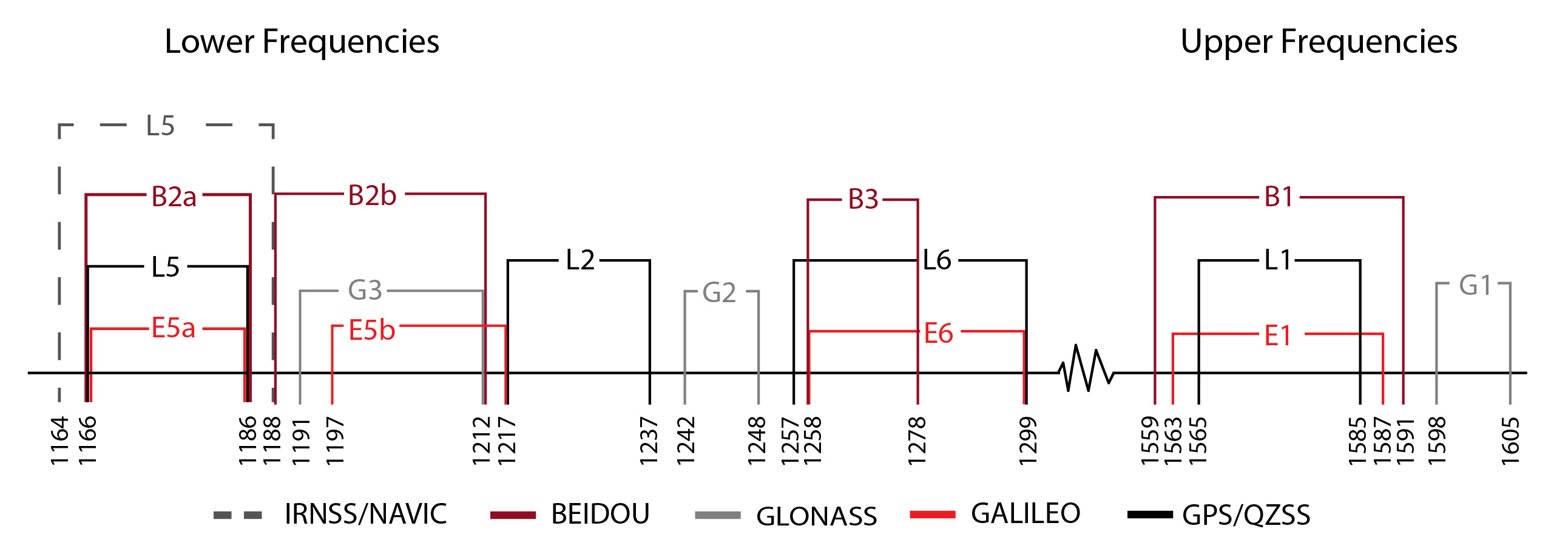
Figure 5.6 and Table 5.1 show the wide range of GNSS frequencies now available across each of the different constellations. Unintentional interference often impacts only a small portion of the entire spectrum, so multi-frequency receivers provide robustness in those situations. Even intentional jamming or spoofing attacks often target only a single frequency or some small subset of frequencies.
| FREQUENCY (MHz) | ||||
|---|---|---|---|---|
| CONSTELLATION | SIGNAL | LOWER | CENTER | UPPER |
| GPS | L1 | 1565.19 | 1575.42 | 1585.65 |
| L2 | 1217.37 | 1227.60 | 1237.83 | |
| L5 | 1166.22 | 1176.45 | 1186.68 | |
| Galileo | E1 | 1563.14 | 1575.42 | 1587.70 |
| E5a | 1166.22 | 1176.45 | 1186.68 | |
| E5(altBOC) | 1166.22 | 1191.80 | 1217.37 | |
| E5b | 1196.91 | 1207.14 | 1217.37 | |
| E6 | 1258.29 | 1278.75 | 1299.21 | |
| GLONASS | G1 | 1598.06 | 1600.99 | 1605.37 |
| G2 | 1242.94 | 1248.06 | 1248.63 | |
| G3 | 1191.80 | 1202.03 | 1212.26 | |
| BeiDou | B1 | 1559.05 | 1575.42 | 1591.79 |
| B2a | 1166.22 | 1176.45 | 1186.68 | |
| B2/B2b | 1197 | 1207.14 | 1217 | |
| B3 | 1258.29 | 1268.52 | 1278.75 | |
| IRNSS/NAVIC | L5 | 1164.45 | 1176.45 | 1188.45 |
| QZSS | L1 | 1573.42 | 1575.42 | 1577.42 |
| L2 | 1226.58 | 1227.60 | 1228.62 | |
| L5 | 1166.22 | 1176.45 | 1186.68 | |
| L6 | 1257.75 | 1278.75 | 1299.75 |
