
Product Information
Product Briefs, Purchasing Guides, Case Studies
ICDs are now independant documents from user manuals and can be found in Technical Documentation
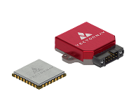
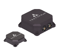
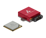
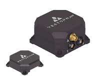
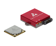
Explore VectorNav's complete product line-up of high-performance IMU and GNSS-aided INS solutions.
View Brochure