Educational Material
1.7 GNSS-Aided Inertial Navigation System (GNSS/INS)
The Global Navigation Satellite System (GNSS) is a satellite configuration, or constellation, that provides satellite signals to a GNSS receiver which can be used to calculate position, velocity, and time. An inertial navigation system (INS) uses an inertial measurement unit (IMU) consisting of microelectromechanical system (MEMS) inertial sensors to measure the system's angular rate and acceleration. Measurements from each of these two systems can be combined using advanced Kalman filtering estimation techniques to form a GNSS-aided INS system (GNSS/INS). This combined system is able to provide position, velocity, and attitude estimates of higher accuracies and with better dynamic performance than a standalone GNSS or INS system can provide.
System Contributions
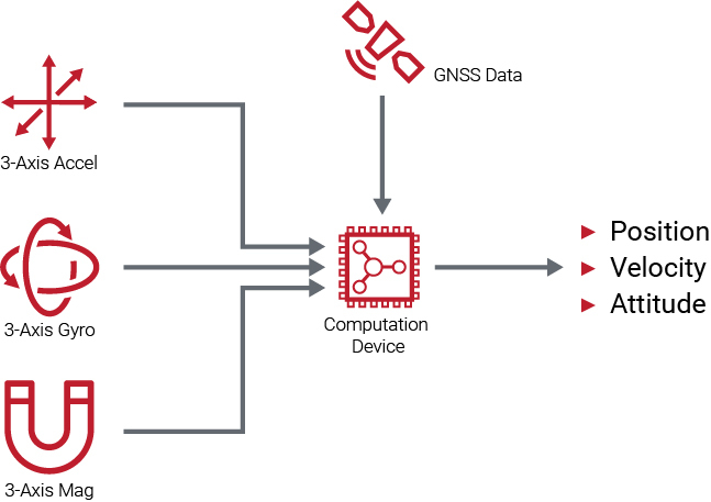
A GNSS/INS system typically includes a 3-axis gyroscope, a 3-axis accelerometer, a GNSS receiver, and sometimes a 3-axis magnetometer to estimate a navigation solution. Each of these sensors contribute different measurements to the GNSS/INS system.
Gyroscope & Magnetometer
Both the gyroscope and magnetometer provide a GNSS/INS system with the same contributions that they provide to an AHRS. The gyroscope angular rate measurements are integrated for a high-update rate attitude solution, while the magnetometer (if used) provides a heading reference similar to a magnetic compass. More information regarding the contribution of these sensors can be found in Section 1.6.
Accelerometer
An accelerometer in a GNSS/INS system measures both the system's linear acceleration due to motion and the pseudo-acceleration caused by gravity. In order to obtain the system's linear acceleration due to motion, the pseudo-acceleration caused by gravity must be subtracted from the accelerometer measurement using estimates of the system's attitude. The resulting linear acceleration measurement can then be integrated once to obtain the system's velocity and twice to obtain the system's position. However, these calculations are heavily dependent on the INS maintaining an accurate attitude estimate, as any error in the attitude causes an error in the calculated acceleration, consequently causing errors in the integrated position and velocity.
GNSS Receiver
A GNSS receiver uses the navigation message sent from the GNSS satellites and tracks the pseudorange and Doppler raw observable measurements to provide a GNSS/INS system with the receiver's position, velocity, and time (PVT). This drift-free PVT solution is used to stabilize the solutions offered by the integrals of the accelerometer and gyroscope.
System Fusion
Both the INS and GNSS can track the position and velocity of the system. An INS typically has reduced errors in the short-term, but larger, unbounded errors over extended periods of time. In contrast, GNSS tends to be noisier in the short-term, but can provide more stability over longer periods of time. When the two systems are integrated together, the GNSS measurements are able to regulate the INS errors and prevent their unbounded growth. On the other hand, an INS can provide a navigation solution at high output rates, while a GNSS navigation solution is typically only updated at rates between 1 Hz and 10 Hz. Combining the measurements from these two systems allows the INS solution to bridge the gap between GNSS updates. A GNSS/INS system often uses a Kalman filter to track an optimal estimate of the system's position, velocity, attitude, gyro bias, and accelerometer bias.
High-Accuracy Pitch & Roll
Unlike the AHRS filter, no assumption regarding the accelerometer measuring only gravity is made. Pitch and roll are still determined by knowing the direction of gravity, but the GNSS measurements make it possible to account for the impact of dynamic motion on the accelerometer readings. Combined with the ability to track accelerometer bias, the dynamic accuracy of pitch and roll in a GNSS/INS system is typically 1-2 orders of magnitude better than that of an AHRS.
Dynamic Alignment
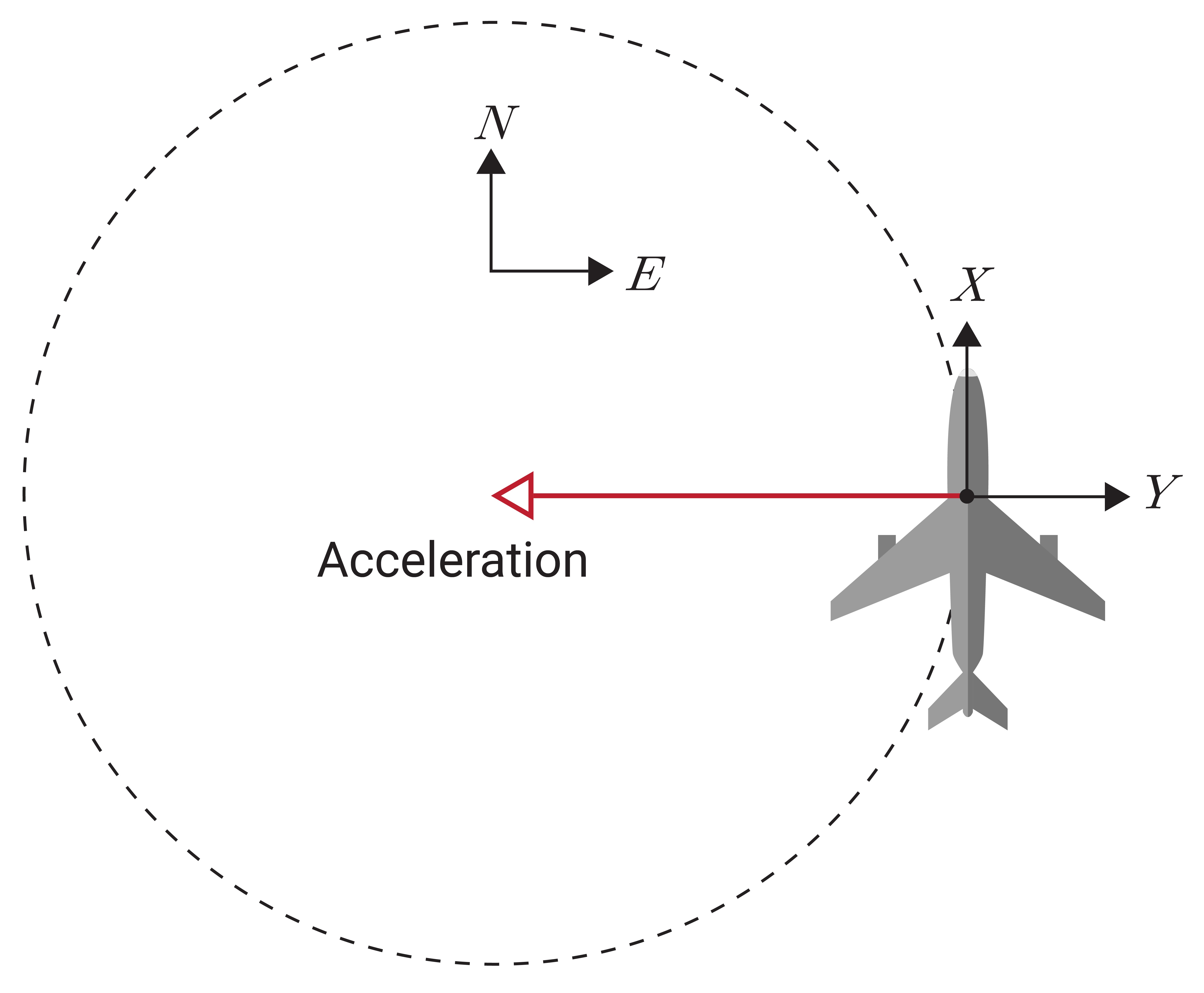
Under sufficient dynamic motion, a GNSS/INS determines heading through a process known as dynamic alignment. The system correlates the acceleration measurements from the accelerometer with the position and velocity measurements from the GNSS receiver and is able to accurately derive the heading through this comparison.
For example, consider an accelerometer that measures that a system is accelerating in the negative y-axis of the vehicle, while the GNSS reports the system is accelerating West, as shown in Figure 1.20. Correlating these two measurements together yields that the negative y-axis must be aligned to West, and so the system must be pointing North.
Some systems---primarily legacy systems---require a specific pattern of motion to achieve dynamic alignment. But all that is required for most modern systems is horizontal acceleration of any type, such as accelerating down a runway at takeoff, driving around the block, or flying a figure-eight. In fact, most smaller vehicles simply need to get up to a decent speed to trigger dynamic alignment; the small fluctuations of a car at highway speed or a Cessna in light turbulence is enough for the Kalman filter to observe heading.
Note that the process of dynamic alignment is not the same as assuming heading is in the same direction as the velocity vector. It is a measure of the true heading of the vehicle, completely independent from course over ground (COG).
Coupling Architecture
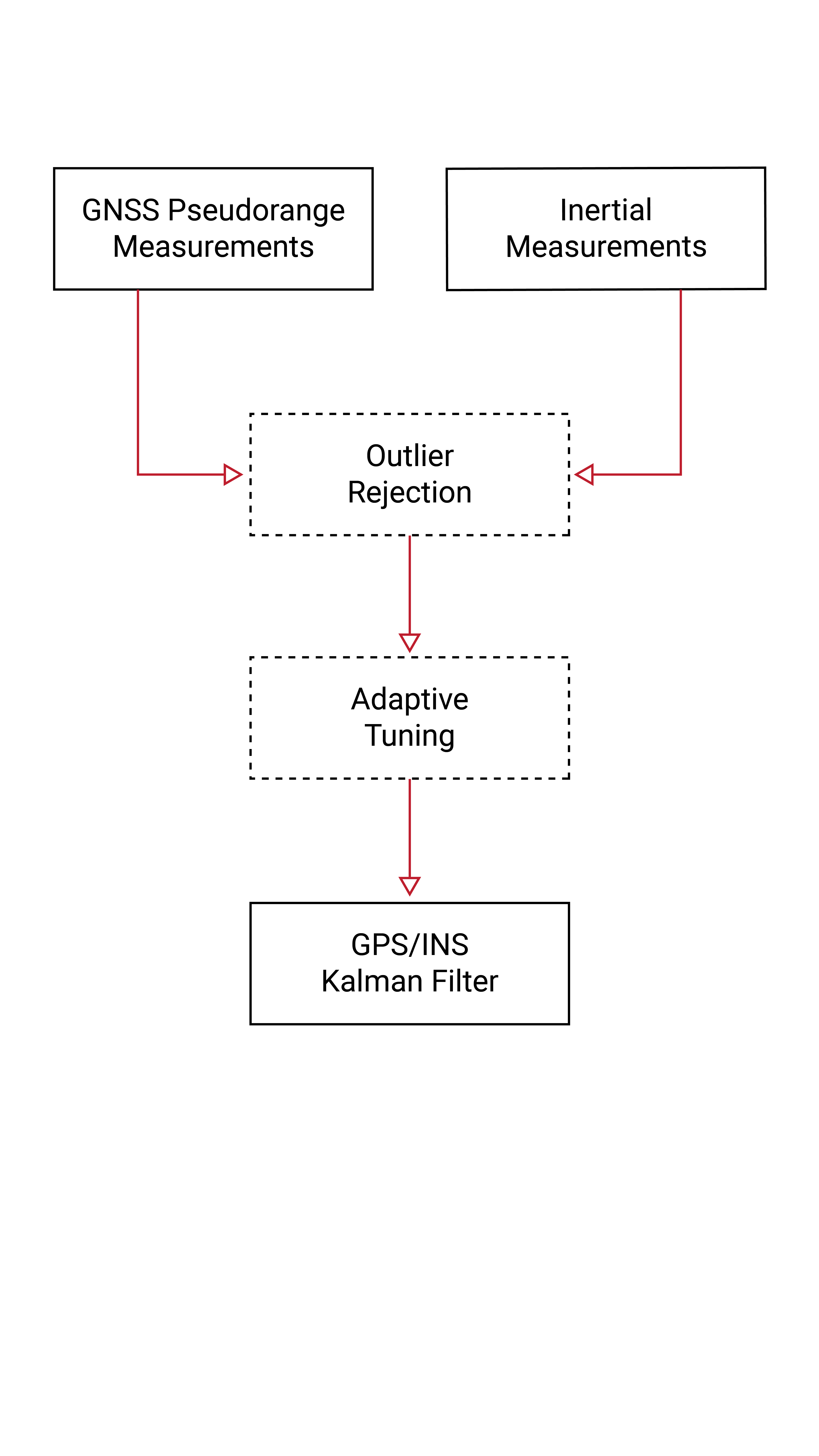
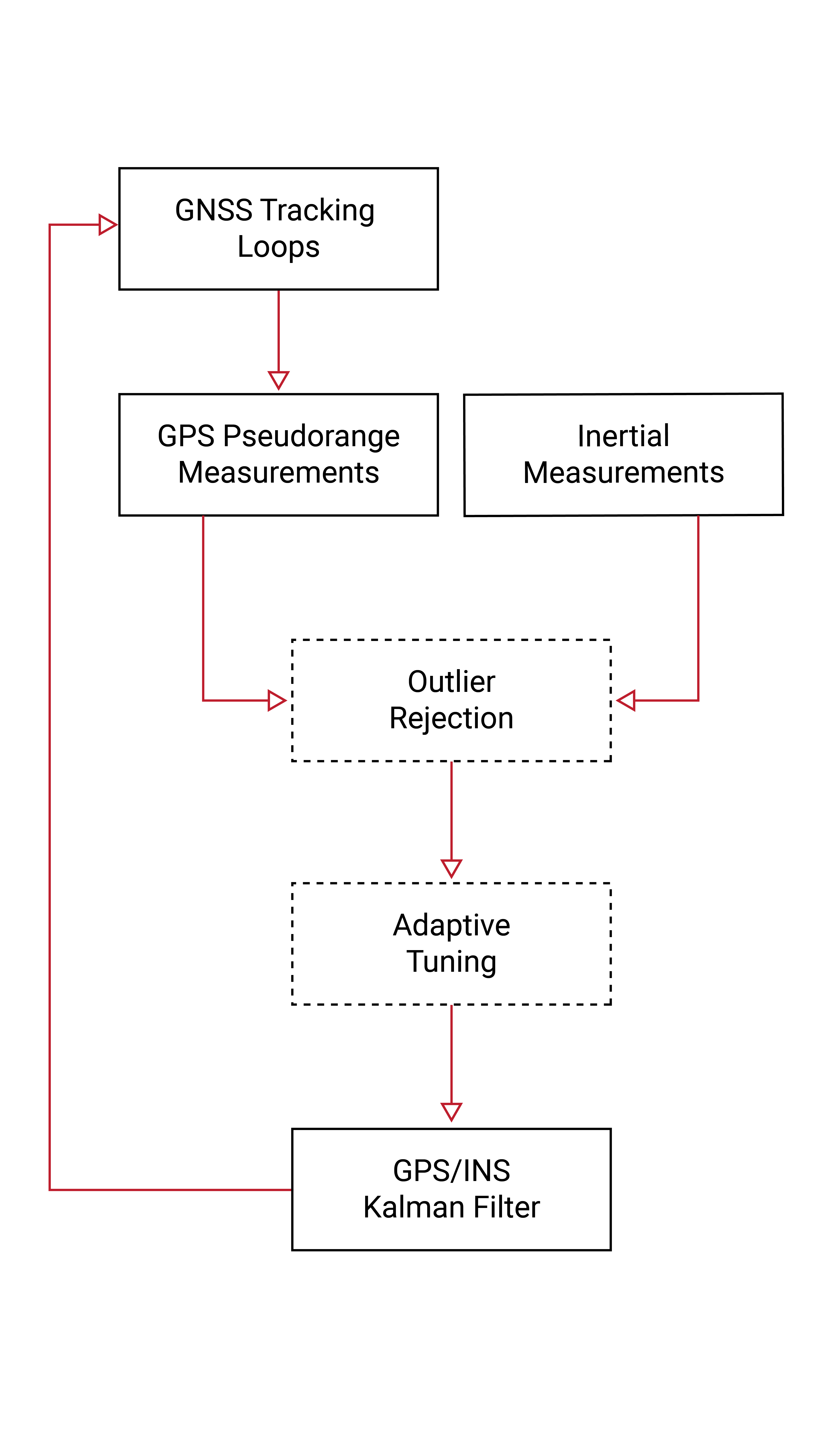
When combining a GNSS and INS system together, there are a few different integration architectures that can be used to couple the measurements from each of the two systems. These different approaches are commonly referred to as loosely-coupled, tightly-coupled, and ultra-tightly-coupled, and are shown in Figure 1.21.
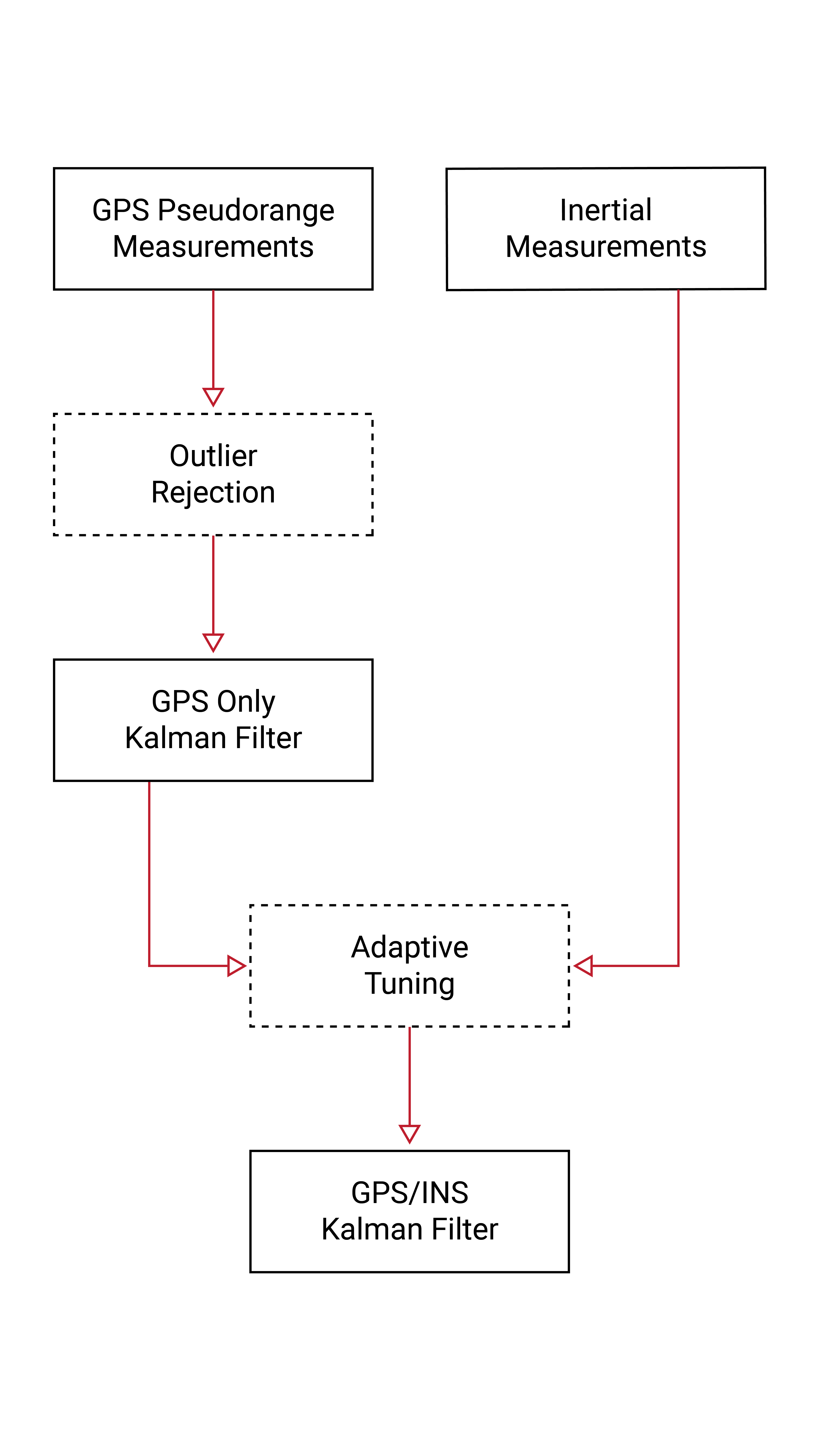
The loosely-coupled GNSS/INS system architecture is the most common integration approach. As shown in Figure 1.21a, this type of integration combines the GNSS navigation solution, consisting of the position, velocity, and time, with the INS navigation solution using an extended Kalman filter. The filter uses the INS measurements to predict the position, velocity, and attitude of the combined system. GNSS measurements are then used to update this prediction and estimate the gyro bias and accelerometer bias in the INS. These estimated biases are used to compensate the raw gyroscope and accelerometer measurements in the INS and improve its integration accuracy. In this approach, a GNSS receiver must have at least four satellites in view to calculate the receiver's position and velocity to send to the extended Kalman filter. If fewer than four satellites are in view of the receiver, the combined system will experience a GNSS outage and default to an INS.
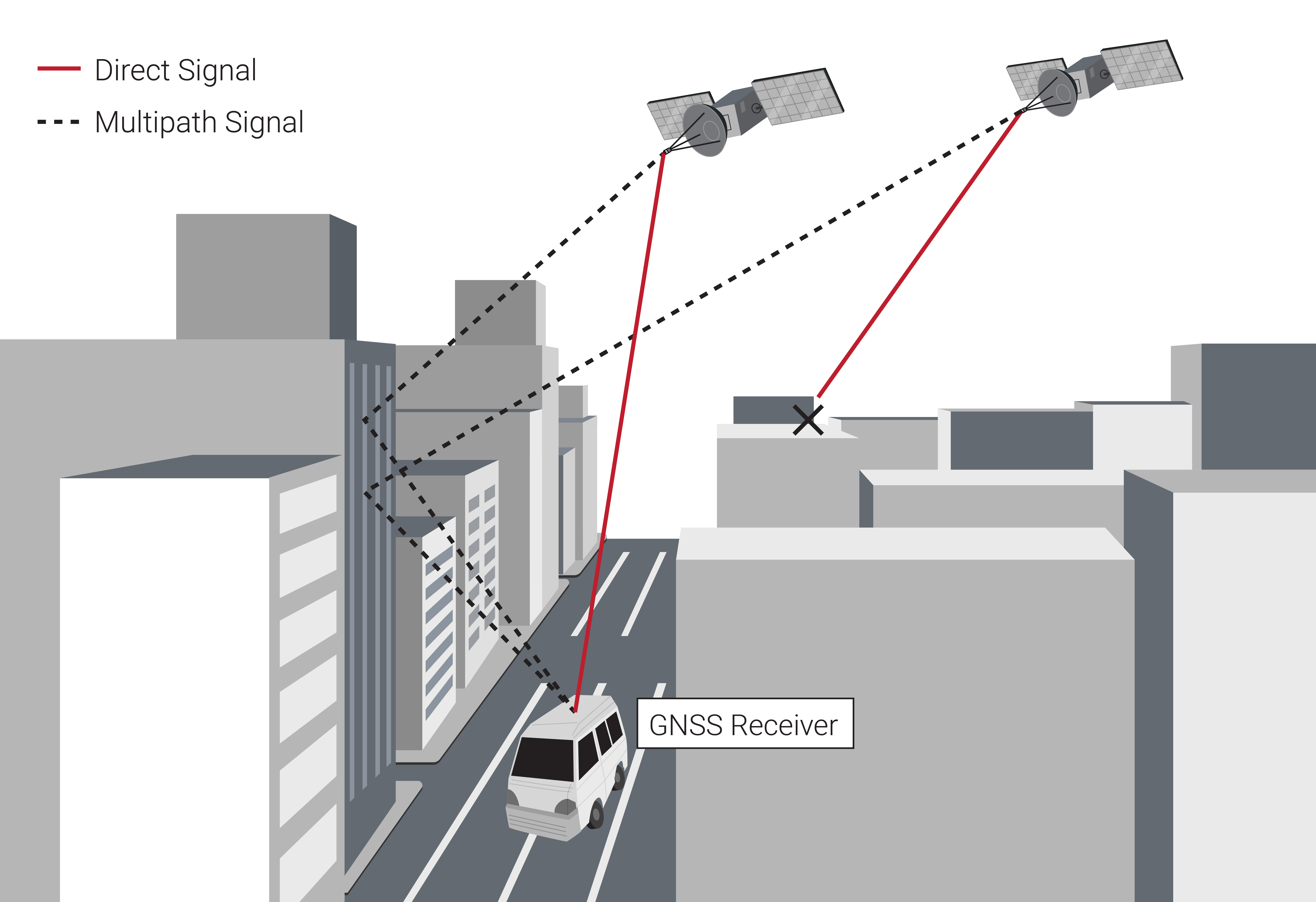
As seen in Figure 1.21b, the tightly-coupled approach for the GNSS/INS system architecture is more closely integrated than that of the loosely-coupled design. This approach does not use the full navigation solution computed by the GNSS, but rather utilizes the raw GNSS pseudorange and Doppler measurements. As shown in Figure 1.21b, the raw GNSS measurements are combined with the INS navigation solution containing the integrated position, velocity, and attitude measurements into an extended Kalman filter. Since this approach uses the raw GNSS pseudorange and Doppler measurements rather than the full PVT solution, a single satellite can provide a useful GNSS update to the system. Due to this, the tightly coupled approach is most useful in applications that only have a partial view of the sky or that are susceptible to multipath error, such as urban canyons.
While the tightly-coupled approach has a potential advantage in restricted visibility environments, there is generally no benefit in clear-sky conditions. Furthermore, the outlier rejection and adaptive tuning algorithms employed (or not) by the GNSS receiver and the INS determine whether there is truly any advantage to tightly-coupled even in an urban canyon. If both a loosely-coupled and tightly-coupled filter were to naively factor in every GNSS measurement, the results of the two would be identical. While it is possible to create superior outlier rejection algorithms in a tightly-coupled scenario, in practice many tightly-coupled systems fall far short of loosely-coupled systems in head-to-head evaluation.
The ultra-tightly-coupled GNSS/INS system architecture is the most closely integrated approach, as seen in Figure 1.21c. Rather than having the GNSS and INS function as independent systems, the INS is used to help drive the tracking loops of the GNSS receiver, which track the carrier signals transmitted from the GNSS satellites. As satellites and the receiver move relative to each other, the INS provides high-rate feedback to maintain a tracking lock, even with a narrower tracking bandwidth than used in a standalone receiver. This narrower tracking bandwidth increases system accuracy and makes the receiver much less likely to track a multi-path signal rather than the true, direct signal from the satellite. However, the ultra-tightly-coupled approach is not as widely used in industry, as such feedback loops introduce new system instabilities and eliminate the redundancy that otherwise independent GNSS and INS systems provide in loosely- or tightly-couple systems.
Challenges of GNSS/INS
While many of the limitations GNSS and INS face as standalone systems can be mitigated by combining them together, there are still a few challenges that come with using a GNSS-aided INS system, including losing the heading information in static or low dynamic situations, the fact that GNSS errors are non-Gaussian and non-zero mean, and the possibility of GNSS outages.
Static or Low-Dynamic Situations
A GNSS/INS system loses observability of heading during low-dynamic or static situations, where dynamic alignment becomes impossible. During short duration periods of low dynamics, the INS can maintain an accurate, though continuously degrading, heading (on the order of 1 min for industrial grade). Most GNSS/INS systems fall back on an integrated magnetometer to continue stabilizing heading, though the issues with magnetic heading experienced in an AHRS system come into play.
GNSS Errors
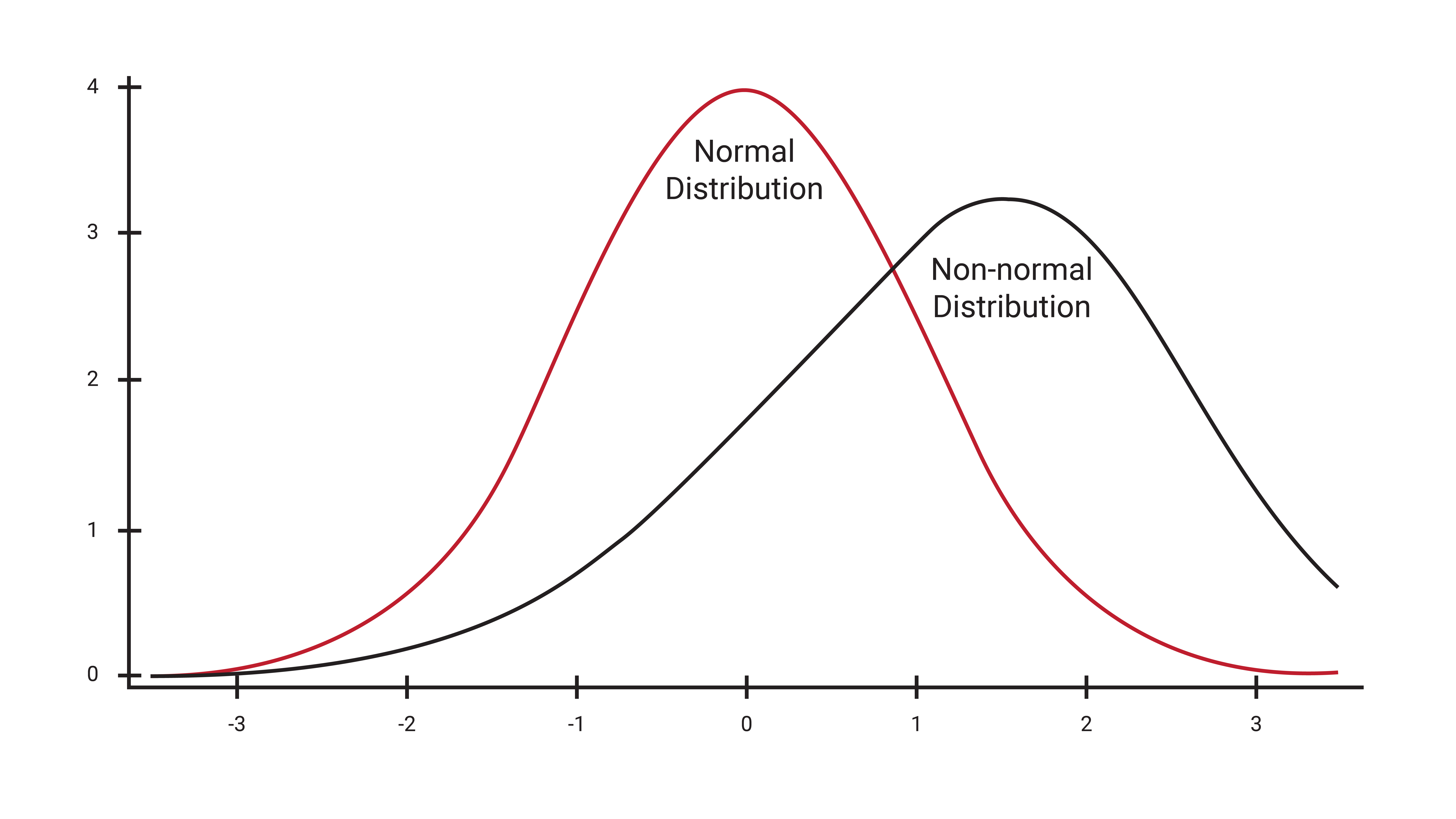
Another challenge a GNSS/INS system faces is that the nature of GNSS measurement errors are non-Gaussian and non-zero mean. Non-Gaussian errors have a distribution that does not resemble that of a bell-curve shape, while non-zero mean errors contain a distribution with a mean that is not equal to zero, similar to Figure 1.22. A critical assumption used to derive optimality of a Kalman filter is that any errors in the system are Gaussian and zero-mean. Since GNSS errors violate this assumption, extra care must be taken when tuning a GNSS/INS Kalman filter to achieve the best performance.
GNSS Outages & Blockages
GNSS outages also pose a problem to a GNSS/INS system and can occur from a signal blockage or a signal interference. A GNSS signal blockage can be caused by anything from buildings to foliage that prevents the signal transmitted by the GNSS satellites from reaching the GNSS receiver, as illustrated in Figure 1.23. Signal interference is caused by a disturbance and can be intentional, such as in the case of jamming or spoofing, or unintentional, such as radio broadcasting signals that create disturbances on the signal. When GNSS outages occur, the GNSS/INS system defaults to an INS, which relies only on the IMU sensors to derive a navigation solution. Depending on the classification of the IMU sensors, using an INS alone to determine the navigation solution could lead to a large drift of the estimate over a short period of time.
